Basic Electronics for Model Railroaders
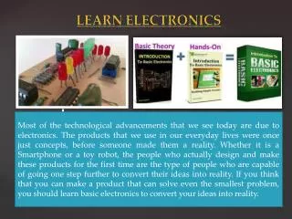
Explore VERY BASIC electronics concepts for model railroads in an easy-to-understand manner. Learn about resistors, capacitors, diodes, LEDs, key formulas, and basic circuits. Discover the essential tools and resources every model railroader should have for troubleshooting electrical and electronic issues.

Basic Electronics for Model Railroaders
E N D
Presentation Transcript
Basic Electronics for Model Railroaders Carl Marchand Suncoast Model Railroad Club Largo, FL
Dedication To Peter J. Thorne, for the guidance and inspiration that led to a career in Electronics and Computer Technology
What We Will Cover VERY BASIC Electronics – easy-peasy; not scary stuff How to troubleshoot electrical / electronic issues. Your Survival Kit – Tools and resources EVERY model railroader should have BONUS – 3 Light Signal Circuit
More Symbols K= Kilo or x 1000, i.e. 1000 Ohms = 1K Ohms M = Mega or x 1,000,000, i.e, 2,000,000 Ohms = 2M Ohms ꭥ = Symbol for Ohms, i.e., 500 Ohms = 500 ꭥ μ = micro = 1/1,000,000 as in 100 microfarads = 100μF
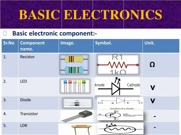
Fundamental Components Resistor Capacitor Diode LED
Key Formulas Voltage = Current x Resistance E = I x R Power = Voltage x Current P= E x I There are two basic electronic formulas to know/commit to memory (or at least write down!)
What is a RESISTOR? Schematic Symbol for Resistor In Model Railroad Electronics resistors are used: to reduce current flow (i.e., lamps and LEDs) adjust signal and/or voltage levels bias active elements (control the turn-on of transistors, integrated circuits, detectors, etc.) Come in a variety of resistance values, rated in Ohms and power capacities, rated in Watts
Resistor Common Use ___ Ohms, ___ Watts What value goes here? 14Volt Power Supply 1.5 Volt 15 mA Lamp
Resistor Common Use ___ Ohms, ___ Watts What value goes here? 14Volt Power Supply Kirchhoff's voltage law (2nd Law) states that the sum of all voltages around any closed loop in a circuit must equal zero 1.5 Volt 15 mA Lamp Series Circuit
Resistor Common Use We will use OHM’S LAW and KIRCHOFF’s LAW to calculate the value of the resistor 1/4 835 ___ Ohms, ___ Watts 12.5 V 0.1875W X 0.015A 12.5 V 833.333 Ohms 0.015A 12.5 Volts Voltage Drop 14Volt Power Supply 1.5 Volt 15 mA Lamp 14 Volts 1.5 Volts Series Circuit 14 Volts minus 1.5 Volts equals 12.5 Volts
What is a DIODE anyway? • A diode is the baseline fundamental semiconductor • Current flows in one direction only • Typical diodes have a Voltage Drop of 0.7 Volts • Primary Component in: • Power Supplies • Detection Circuits • Constant Lighting
What is a DIODE anyway? PARTS OF A DIODE ANODE CATHODE K A DIRECTION OF CURRENT FLOW Current flows AGAINST the arrow
Constant Lighting • http://www.circuitous.ca/xConstLight.html
The Ubiquitous LED • LED = Light Emitting Diode • Symbol similar to standard diode • Advantages: • Draws very low current • Little or no heat dissipation • Comes in a myriad of sizes • Useful in scales from Z-Scale up! • Extremely long lasting • Key advancement in Model RR lighting
The Ubiquitous LED SMD – Surface Mount LEDs 3mm LEDs 5mm LEDs
Basic Circuits Series Circuit Current flowing through each component is the same as the total (IT) The sum of all the voltage drops equals the Source Voltage (Vs)
Basic Circuits Series/Parallel Circuit Parallel Circuit IC I 1 T = 210mA This LED is on when Vs is reversed IC 2 IC = 200mA = 10mA = 10mA 3 The Voltage Source is the same across each branch Each branch has its own Current Flow The sum of Ic1 and Ic2 or Ic1 and IC3= total current of the circuit
Handy – Dandy Tester - + - +
Circuitron Tortoise™ • The most popular switch machine in Model Railroading • Two SPDT switches are built-in • Motor’s DC resistance is 600 Ohms – low current draw. • Can be controlled in various ways including DC panel switches or DCC stationary decoders.
Circuitron Tortoise™ • The SPDT switches can be used for: • Signal System Control • Switch Position Status. • Powered Frog Routing – (one of the highest uses of the SPDT)
Examples Why / how does this wiring of LEDs and the Tortoise ™ work?
The Capacitor A capacitor is two plates separated by a dielectric (old school definition). Stores energy in a static electric field (similar to a very short term battery) Electrolytic and non-electrolytic types Polarized and non-polarized types Draws current while charging. Supplies current when discharging. Smooths out power in DC power supplies (reduces AC ripple by “filtering out” the variation in current. Unit of Measure = Farad or microFarads (μF)
The Capacitor By Eric Schrader from San Francisco, CA, United States - 12739s, CC BY-SA 2.0 Allows AC current to pass through it Prevents DC current from passing through it Se
Basic Capacitor Use Courtesy of Electronics StackExchange https://electronics.stackexchange.com/questions/175098/where-exactly-does-the-ground-line-go-in-an-ac-dc-power-supply Courtesy of Electronics Area https://electronicsarea.com/basic-power-supply-block-diagram/
Recommended Tools Wire Cutters Wire Strippers Needle Nose Pliers Variable Temp Soldering Iron Electronic Solder (Kester "44" rosin core, SN63PB37, .015" diameter, part number 24-6337-0007) Desoldering Pump (aka “Solder Sucker”) TwoMultimeters Jumper Lead Kit Experimenters Breadboard
Why TWO Meters? In some cases, you may need to measure Current (I) and Voltage (E) simultaneously • Meter Requirements: • Measure DC Voltage /Current • Measure AC Voltage / Current • Measure Resistance
Troubleshooting Dead Track Good Good Rail Joiners Good Faulty track section RECOMMENDED: to find the faulty connection(s) keep the locomotive in the bad section and with power applied to the working track sections, measure the VOLTAGE across the rail joiners. The bad connection will show a voltage, the good ones will not. BAD
What is a Transistor? N P N A transistor is a semiconductor device used to amplify or switch electronic signals and electrical power. Made of semiconductor material usually with at least three terminals for connection to an external circuit. A voltage or current applied to one pair of the transistor's terminals controls the current through another pair of terminals. Due to its design, the output power can be much higher than the input power, allowing it to act as an amplifier.
Fundamental Transistor Use Used as a SWITCH Used as an AMPLIFIER