Download
1 / 42
430 likes | 606 Vues
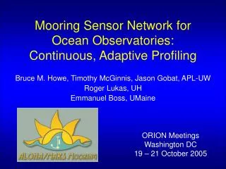
Mooring Sensor Network for Ocean Observatories: Continuous, Adaptive Profiling. Bruce M. Howe, Timothy McGinnis, Jason Gobat, APL-UW Roger Lukas, UH Emmanuel Boss, UMaine. ORION Meetings Washington DC 19 – 21 October 2005. Outline. Introduction and motivation Moorings

E N D
Mooring Sensor Network for Ocean Observatories: Continuous, Adaptive Profiling Bruce M. Howe, Timothy McGinnis, Jason Gobat, APL-UW Roger Lukas, UH Emmanuel Boss, UMaine ORION Meetings Washington DC 19 – 21 October 2005
Outline • Introduction and motivation • Moorings • ALOHA-MARS Mooring design • Questions and issues • Main point • we are developing ORION sensor network infrastructure and making many decisions on our own • ideally coordinated • what can this committee do to help in the future? • too late for this particular project – but suggestions still welcome!
Introduction – 1 • A major effort and cost in the lifetime of an ocean observatory system will be in the sensor networks • Here – the sensor network infrastructure part • Terminology: • Backbone infrastructure provides primary junction boxes/nodes • Sensor networks = (sensors/instruments + sensor network infrastructure)
Introduction – 2 • Sensor network infrastructure • everything between sensors and backbone nodes • called science instrument interface modules (SIIMs) • definitions and terminology still evolving • Includes • “secondary” cable and junction boxes, • connectors, in-line converters, “pucks”, • sensor “platforms”, moorings, winches, fixed and mobile (profilers, AUVs, gliders, rovers) • down-borehole arrays, moles, … • associated O&M • and more - the user tool kit
Need for profiling moorings in ORION and ocean observatories • Reduce temporal and spatial aliasing in vertical sampling of the ocean, e.g., at tide and internal wave frequencies and space scales • Deliberately intensive sampling of fine vertical structure — Meddies/coherent eddies, biological thin layers, overflows, etc. • Sampling of episodic or otherwise non-stationary flow • Less expensive than many fixed instruments
Example:Fully loaded mooring (Daly et al. 2005) • Two platforms for remote sensing and point instruments • Two profilers • Tomography source and receiver • Bottom instrument suite • Two moorings better? • Fixed • Profiling (one unit) • More robust?
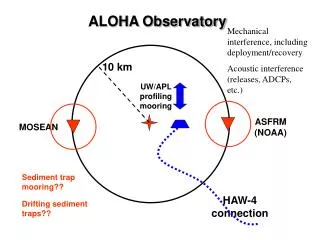
ALOHA-MARS Observatory Mooring • Features • Enables adaptive sampling • Distributes power and communications capability throughout the water column • ROV servicing • Major Components • Subsurface float at ~165 m depth with sensor suite and junction box • Mooring profiler with sensor suite that can “dock” for battery charging, continuous two-way communications • Electro-optical-mechanical mooring cable • Seafloor sensor suite & junction box • Deployments • 2006 on Seahurst Observatory in Puget Sound, 30 m depth • 2007-2008 on MARS in Monterey Bay, 900 m depth
User Requirements • Current profiling for entire water column • Near continuous in-situ profiling from near surface to seafloor with CTDO2, ACM, bio-optics • 1 cycle per tidal half cycle • Non-stop run time > 3 days • Duty cycle > 90% • Depth range controllable • Provide extra Science User Connectors with “standard” power and data interface on float and seafloor
System Requirements • Compatible with MARS/NEPTUNE/VENUS/ORION global buoys (and others) power and data interfaces • Provide 48Vdc and 400Vdc power and 100BaseT communications at Science User Connectors; provide interface for RS-232 sensors at 12 V and 48V • Timing: ~1 ms required, ~microseconds desired (future acoustics) • ROV-serviceable secondary junction boxes and connections • Operational life of > 2 years • Located 1.5 km from MARS node to allow ROV access to MARS node and other instruments
Wish List • Profiler (and other active components) install/remove/service by ROV • Larger profiler, larger payload, faster • Higher data rate (> present 1200 baud) communication with profiler • More power transfer • Multiple docks and profilers on a single mooring • More sensors • Broadband hydrophone/transducer array, fixed, profiling • Bio-optics • Still/video • pCO2
Float and MMP ROV-serviceable instrument platform Inductive power coupler MMP
Subsurface Float Instrument SIIM bays Ti center post in slot 2ndary J-box electronics (with IPC, SIM, ADCP, camera) Guard rail SIIM ROV-mateable connectors Float, 3000 lbs buoyancy ROV-positioning pins Swivel, 12-elect Termination (with E-O converter) Cable, 0.825-inch, 4 fiber 6 conductor, kevlar, fishbite
Float SIIM Lifting bale Electronics (will replace ADCP in this figure) ROV-mateable connector CTDs, Bio-optics Latch ADCP and camera will be permanently mounted on float, use 2ndry node ROV “fork” slots
McClane Mooring Profiler (MMP) • 6000 m depth rating • Mission sampling programmable • Resistant to cable fouling • 1 Mm of travel per battery charge (50 days) • Standard sensors • CTD • 2-d Acoustic Current Meter (ACM) • ~40 units sold
McLane Mooring Profiler Modifications • Add inductive power transfer • Rechargeable Smart-Li-Ion batteries, 90% duty cycle (4 days on, 4 hr charge) • Add inductive communications – Sea-Bird 1200 baud real time • Add controller to interface to • MMP controller • Comms inductive modem • Battery monitor • Sensors (BB2F, etc) • New drive wheel - larger EOM cable (~21 mm) • Keep 0.25 m s–1 speed • Sensors: Seabird CTDO2, FSI Acoustic Current Meter (ACM), WetLabs Red/Blue Backscatter and Fluorometer (BB2F) • Lengthen, add sphere
Inductive Power Coupler • S&K Engineering • Need < 2 mm gap • Efficiency ~70% • 200 W transfer • 10 kHz • MMP electronics includes 24 V battery charging • Concerns: • Biofouling • Robustness • Docking • Holding profiler in place during charging Primary on cable Secondary on MMP Attach to MMP, 2-inch spring
Seafloor Secondary Node • Stainless steel electronics case (on-hand, full ocean depth) • PC-104 controller • 400-48V dc (Vicor) • MOSFET and deadface switches, software controlled • Ground fault detection a la MARS • 8-port 100baseT Ethernet switch ROV-mateable connectors Electronics ROV “fork” slots Removable ballast Fiberglass grating
Seafloor cable • Deploy using MBARI sled (need more capability in future) • Use ODI connectors • Use in-line electrical-optical converters at each end for 1.7 km long run (comms, precise time 1 pps) • 1300 W-km
Small cable power delivery capacity Source Wire Cross Wire Power Voltage Gauge Section Resistance Capacity VDC AWG mm2 Ohm km-1 Watt-km 2000 16 1.3 14 32500 2000 24 0.2 75 6087 1000 16 1.3 14 8125 1000 24 0.2 75 1522 400 16 1.3 14 1300 400 24 0.2 75 243 48 16 1.3 14 19 48 24 0.2 75 3 Trade capability, distance, ROV/other deploy costs, cable cost, …
Electrical-Optical Conversion • Allows use of standard ROV connector with copper conductors for Ethernet communications over long distances • Cost significantly less than E-O hybrid connector
Electrical-Optical Conversion • ROV mateable electro-optical connectors very expensive (~$30k), not likely for instrument connection • ROV mateable electrical connectors lower cost (~$6k) and will be used on MARS, VENUS, NEPTUNE and ALOHA-MARS • Fiber optic cables are required for high rate data transmission > 100m • Transmission distances up to 100 km • COTS ethernet electrical-optical converter available for operation in 10 kpsi oil (~$2k)
Power Budget - Watts Source Power 1200 Seafloor Loads Infrastructure 40 Basic Sensors 25 Guest Sensors 200 Float Loads Infrastructure 30 Battery Charging (or Winching) 321 Basic Sensors 37 Guest Sensors 131 Transmission and Conversion Loss 415 Total 1200
Deck Frame Requires DP ship Mooring winch Trawl winch Load transfers Anchor first Rail system – moves float and mooring cable in and out Lays on fantail Bolts to 2-ft pattern Float and Ti post locked during prep
Deployment scenario • ROV deploys seafloor cable and secondary node with SIIM, 20 m clear of Love Point (done well before mooring deployment) • Deploy anchor, releases, and mooring using EOM cable winch • Attach MMP • Stop with top termination in-board of block (A-frame out) • Attach grip/chain to take load off termination, remove last section of cable (used as leader on the cable drum) • Attach inductive coupler to cable, connect • Attach swivel/Ti post to termination • Attach trawl wire to termination, laying through block, take strain • Guide into float slot, move float out, lock, release strain • Connect electronics, test • Attach acoustic release to 2-m nylon spring line on float ring • Attach acoustic release to 15-m nylon spring line attached to trawl wire • Move float and cable outboard on deployment frame with A-frame following • Take strain, swing out, lower to 3 m above bottom (pinger?) • Move to Love Point, drop • ROV moves bottom node closer, connects mooring, puts bottom SIIM on mooring, clears lowering line, inspects
Recovery scenario • ROV disconnects bottom SIIM and node, moves clear of mooring (recovers if necessary), attaches recovery line to float ring (detail?) if possible • Ship recovers line float (recovers anchor?), or uses acoustic release and snaps ring • Take strain and lift using trawl line (with nylon leaders, shackle through block?) • Swing float and post into deck frame and lock, release strain • Disconnect electronics • Connect trawl wire to Ti post ring • Disconnect Ti post from float, take strain, and swing out • Lift post high, attach grip below inductive power coupler and cable termination, chain, release strain • Disconnect swivel/post inductive power coupler from cable • Attach trawl winch to grip, pull up to block • Thread termination through block, attach to mooring winch leader • Take strain • Release trawl line from grip and remove latter • Pull in mooring cable unitl MMP shows; recover, continue • Recover releases (and anchor if the case)
General Questions • Interfaces in sensor network infrastructure – connectors, software, protocols, metadata, time stamping, geo-referencing, PMACS, DMAS, OCS, … • Standardization (e.g., SIIM connectors) • Costs • Development takes time, money – testing, and more money • Need ROVs, DP ships, and O&M structure • Reliability and cost/benefit study
Specific Questions/IssuesALOHA-MARS Mooring • Review all Interfaces • Evaluate Risk and mitigation • MMP IPC and docking – will test in January • Float system (new handling) • Electrical noise – more filtering, shielded TP, • Integration – will test in April at Seahurst • Contingency during deployment • Concerns • Project originally 3 years, now 5 years – extra cost • Extra cost for MBARI ROV, user fees? Other? • Reworking timeline and budget now
Junction BoxesSubsurface Float and on the Seafloor • Inherited from NEPTUNE/MARS development • Node Controller hardware and software • Shore power control and monitoring, archiving, GUI • Load control – switching, over current, ground fault • DC-DC converters • ROV mateable connectors • New Development • Small Ethernet switch • Ethernet – RS-232 conversion • Ethernet electrical-optical conversion
Other “SIIMs” • Electro-optical conversion • Ethernet, metadata, power interface
Long term issues • SENSORS and NEW APPROACHES • Sensor network infrastructure: • moorings/boreholes/distance/observatories • small diameter cables, laying • underwater ROV-mateable connectors, in-line convert • AUVs, rovers, moles - docks/tethers • Navigation and communications of mobile platforms • Work towards all robotic, reliable (cf. NEMO) • Need to bring in oil and military expertise • An overall architecture • Planning tools for users – the cost function • Research ship and ROV capabilities • Need to develop and gain EXPERIENCE
Other users • Jeff Nystuen – acoustic rain gage (and general ambient sound) • Peter Worcester – short VLA • Ken Smith – rover • Tom Sanford – HPIES • John Horne – fisheries sonar
Junction BoxesSubsurface Float and on the Seafloor • 4 User Connectors • Data Communications • 10/100BaseT • RS-232/422 (?) • Power - ~200 W total • 400 VDC (? no large or remote loads) • 48 VDC • 12 VDC (? probably more common) • Installed Sensor Suite • 2 x CTDO2 • Optics – transmissometer, fluorometer, CDOM, other (?) • ADCP (on Float) • Video on Float and Seafloor, still on profiler (goal)
Observatory – Instrument Interface • Embedded Device Servers • 10/100BaseT Ethernet • Multiple RS-232 ports • Memory space for metadata/embedded website • TCP, UDP, SNMP, DHCP, etc • Auxiliary I/O lines • …….or could have multi-port serial hub in the J-Box and use serial through the User Science Connectors
Science Instrument Interface • Present – for NEPTUNE, still based on Feasibility Report • Multi-pin ROV-mateable connector • 400 V and 48 V (pins for each) • Ethernet 10/100baseT • Precision timing 1 microsecond • Needs Review, iteration with community
Float – secondary node ADCP Attitude sensor Inductive power coupler Inductive modem Video camera with lights Float - SIIM CTDO2 – Dual Optical backscatter, two wavelengths, fluorometer Float Light, radio, ARGOS Anchor - SIIM CTDO2 – Dual Optical backscatter, two wavelengths, fluorometer Anchor Profiler CTDO2 Optical backscatter, two wavelengths, fluorometer 2-d ACM Sensors