Download
1 / 14
150 likes | 424 Vues
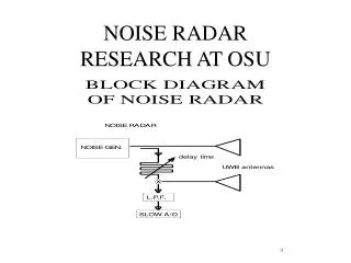
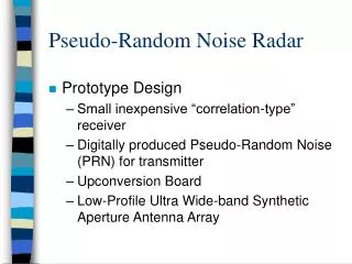
Pseudo-Random Noise Radar. Prototype Design Small inexpensive “correlation-type” receiver Digitally produced Pseudo-Random Noise (PRN) for transmitter Upconversion Board Low-Profile Ultra Wide-band Synthetic Aperture Antenna Array. PRN Generator. The heart of the system.

E N D
Pseudo-Random Noise Radar • Prototype Design • Small inexpensive “correlation-type” receiver • Digitally produced Pseudo-Random Noise (PRN) for transmitter • Upconversion Board • Low-Profile Ultra Wide-band Synthetic Aperture Antenna Array
PRN Generator • The heart of the system
PRN Generator (cont’d) • PC Controlled • Produces two identical pseudo-random waveforms with a user-defined delay between. • Through software, delays can be manipulated to scan entire delay span, partial delay span, or any points therein. • Bandwidth of output noise dependant only on clock-speed of PRN circuit
Upconverter • Basic circuit to convert base-band noise to transmission spectrum of 3 - 3.8GHz.
Optional BPF Filter Board • Can be used to replace Upconverter if large amplification of PRN harmonics is used. • Currently Not used in system
Antenna Array • Gain of 8+ dBi • Side-by-side elements can be used for isolated measurements (SAR) due to high isolation. (20dB 1st Adjacent - 30dB 2nd Adjacent) • Usable Bandwidth on order of GHz
Receiver • Small - inexpensive • Each channel only requires mixer chip, op-amp chip, RF amplifier chips and discrete components (resistors etc) • Analog integration allows data collection on the order of milliseconds, and reduced noise through averaging. • Preliminary tests show minimum detectable signal at -80dBm.
First System Test (cont’d) • SNR non-optimal due to drastic op-amp output drift with temperature • Problem remedied with low-drift op-amp • No range data taken yet after improvement, but 45dB reduction in noise floor recorded
From here... • Fabrication of improved PRN Generator will provide 7 inch downrange steps to a maximum of 280 feet. • 4 Antennas and Receivers increased to 40 for Synthetic Aperture Imaging • Other possible applications for PRN radar