Download

1 / 38
611 likes | 1.4k Vues
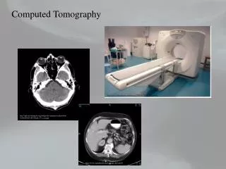
Computed Tomography. Computed Tomography. Introduced in 70’s Principle: Internal structures of an object can be reconstructed from multiple projections of the object. Philips CTVision Secura. Mechanism of CT. X-ray tube is rotated around the patient

E N D
Computed Tomography • Introduced in 70’s • Principle: Internal structures of an object can be reconstructed from multiple projections of the object
Mechanism of CT • X-ray tube is rotated around the patient • Radiation transmitted through the patient is absorbed by a ring of detectors • Absorbed radiation is converted to an image Detectors
Detectors • Scintillation crystals • Xenon-gas ionization chamber
Scintillation Crystals • Materials that produce light (scintillate) when x-rays interact • Similar to intensifying screen • Number of light photons produced a energy ofincident x-ray beam • Light photons need to be converted to electrical signal
Ionization Chamber • X-ray ionizes xenon gas • Electrons move towards anode • Generates small current • Converted to electrical signal
Attenuation • Reduction in the intensity of an x-ray beam as it traverses matter, by either the absorption or deflection of photons from the beam
Pixel - Voxel • Pixel - picture element • Voxel - volume element
Image Display: Windowing • Usual CRT can display ~256 gray levels • 2000 CT numbers • Select the CT number of the tissue of interest, then range of ±128 shades
Cone Beam CT • Uses cone shaped x-ray beam. • Beam scans the head in 360 degrees. • Raw data are reformatted to make images
Benefits of Cone Beam Imaging • Less radiation than multi-detector CT due to focused X-rays (less scatter) • Fast and comfortable for the patient (9 to 60s) • Procedure specific to head and neck applications • One scan yields multiple 2D and 3D images
Coronal Sections • Zygomatic Arch • Lat. Pterygoid plate • Optic canal • Sphenoid sinus • Soft tissues of nasopharynx
Frontal bone (orbital plate) • Ethmoid air cells • Middle concha • Maxillary sinus • Inferior concha
Vomer • Ramus • Follicle of molar • Gr. wing of Sphenoid • Tongue • Mylohyoid m
Magnetic Resonance Imaging • Three steps of MRI • MRR • Magnetic Field • Radio-frequency Pulse • Relaxation
Application of RF Pulse Relaxation
Spin or Angular Moment • 1H, 14N, 31P, 13C, and 23Na has nuclear spin • They spin around their axes similar to earth spinning around its axis • Elements with nuclear spin has odd number of protons, neutrons
Magnetic Moment • When a nucleus spins, it has angular momentum • When the spinning nucleus has a charge, it has magnetic dipole moment • Moving charges produce magnetic fields
Hydrogen Nucleus • Most abundant • Yields strongest MR signal
Radiofrequency Pulse • RF pulse is an electromagnetic wave • Caused by a brief application of an alternating electric current
Receiver Coils • Send or “broadcast” the RF pulse • Receive or “pick up” the MR signals • Types: Body coils, head coils, and a variety of surface coils
Relaxation • This is the process that occurs after terminating the RF pulse • The physical changes caused by the RF pulse revert back to original state
T1- Spin Lattice Relaxation • At the end of RF pulse, transversely aligned nuclei tend to return back to equilibrium • This return to equilibrium results in the transfer of energy
T2- Spin-spin Relaxation • While the nuclei are in transverse phase, their magnetization interfere with each other. • This interference leads to the loss of transverse magnetization.
Magnetic Field Strengths • Measured in Tesla or Gauss • Usual MRI field strength ranges from 0.5 to 2.0 Tesla • Earth’s magnetic field is about 0.00005 Tesla (0.5 Gauss)