Download
1 / 15
150 likes | 328 Vues
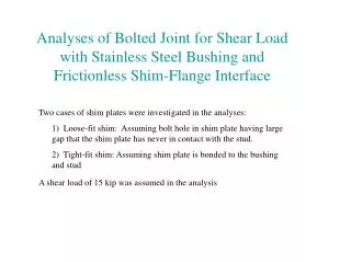
Analyses of Bolted Joint for Shear Load with Stainless Steel Bushing and Frictionless Shim-Flange Interface. Two cases of shim plates were investigated in the analyses: 1) Loose-fit shim: Assuming bolt hole in shim plate having large gap that the shim plate has never in contact with the stud.

E N D
Analyses of Bolted Joint for Shear Load with Stainless Steel Bushing and Frictionless Shim-Flange Interface Two cases of shim plates were investigated in the analyses: 1) Loose-fit shim: Assuming bolt hole in shim plate having large gap that the shim plate has never in contact with the stud. 2) Tight-fit shim: Assuming shim plate is bonded to the bushing and stud A shear load of 15 kip was assumed in the analysis
FEA Model A286 stud Coupling Uz Coupling Ux, Uy, and Uz INCO 718 washer G-11CR washer Flange stellalloy 316 SS shim w/ ins.break A286 spherical washer set 316LN ss bushing A286 hex nut Coupling Ux, Uy, and Uz Fixed support
Assumptions: • Except frictionless shim-flange contact surfaces, all compressive interfaces under preload are continuous (identical nodes) instead of bonded contacts (un-identical nodes) in order to avoid the contact penetrations that affect the joint stiffness. • For stability, the stainless steel bushings were glued to the flange but have frictionless contact with the A286 stud. The hex nuts are glued to the stud without any tolerance. • The spherical washer sets were modeled by equivalent short cylinders. • The thickness of shim was formed by 1/7 of G-11CR insulation and 6/7 of 316 SS. The equivalent smear material property was assumed. • For stability of shim plate, the shim was glued to the lower flange in the loose-fit shim case. In the tight-fit shim case, the shim plate was bonded to the middle bushing and the stud • The lower flange stellalloy was fixed at the bottom surface. The upper flange stellalloy was coupled in the vertical direction on the top surface nodal points. Couples are applied at two side faces of the stellalloy to form a cyclically symmetric model. • In the global coordinate system, y-axis is in the poloidal direction and z-axis is parallel to the stud axis. • The 15 kips shear load was applied on the side surface of the upper flange stellalloy. • All analyses used the room temperature material propertied as shown on next slide.
Shear Load - Deformed Shapes with Undeformed Edge ▪ Shim bonded to the stud will reduce the shear displacement of the bolt joint. ▪ With more realistic contact (no tension), the tight-fit shim will not be that effective. Tight-fit shim Loose-fit shim Undeformed shape Deformed shape Scale factor = 60 Unit in inch
Shear Load - Deformed Shape with Undeformed Edge ▪ For frictionless shim, the primary displacement is in the shear force direction Loose-fit shim Tight-fit shim Undeformed shape Deformed shape Scale factor = 60 Uy Usum Usum Uy Unit in inch
Shear Load - von Mises Stress in Flange Stellalloy ▪ High local stress at edge of hole is mainly due to the deformed shape of stud ▪ The loose-fit shim produces much higher local stress Tight-fit shim Loose-fit shim Unit in psi
Shear Load – Stress Components in Flange Stellalloy ▪ The Sy stress is caused by the bearing pressure from the stud ▪ The Sz stress is due to the bending of stud. If the SS bushing is not bonded to the flange, the Sz will be smaller. Loose-fit shim Tight-fit shim Unit in psi
Shear Load – von Mises and Axial Stresses in Stud ▪ The maximum von Mises stress is the resultant of shear, bearing, and axial compression near the lower edge of the upper bushing Tight-fit shim Loose-fit shim Deformed shape Scale factor = 60 Sz Seqv Sz Seqv Unit in psi
Shear Load – Shear and Bearing Stresses in Stud ▪ The shear and bearing stresses are peak near the lower edge of upper bushing Tight-fit shim Loose-fit shim Tensile stress is the result of bonded contact Deformed shape Scale factor = 60 Syz Sv Syz Sv Unit in psi
Shear Load - von Mises Stress in Bushing ▪ The maximum stress locations are different, one in the upper bushing and the other in the lower bushing. ▪ The middle bushing in the case of tight-fit shim deformed with the stud. Tight-fit shim Loose-fit shim Deformed shape Scale factor = 60 Max. stress locations Seqv Seqv Seqv Unit in psi
Shear load - Contact Pressure on Bushing Tight-fit shim Loose-fit shim Max. pressure Max. pressure Deformed shape Scale factor = 60 Unit in psi
Shear load - Contact Pressure on Shim Plate ▪ The stress in the shim is due to the assumption that shim is bonded to the middle bushing and stud Tight-fit shim Loose-fit shim Upper surface Lower surface No contact pressure on shim plate Deformed shape Scale factor = 60
Shear load - Contact Status on Shim Plate Loose-fit shim Tight-fit shim Upper surface Lower surface Contact status: 3-closed and sticking 2-closed and sliding 1-open but near contact 0-open and not near contact
Discussions: • The analyses intend to observe the structural behaviors of bolt joint using stainless steel bushing when the shear load on the joint is greater than the frictional resistance induced by the bolt preload. • The tight-fit shim produced smaller displacement, however, the bonded contact of stud and shim is practically difficult to achieve in the design so the actual displacement may be between the two cases. • The lateral stiffness of the joint is dominated by the bending and shearing stiffness of the stud as well as the contact pressure on the bushing. • By replacing the G-11 bushing to the SS bushing did the shear displacement reduced from 0.0107-in to 0.0065-in • The total displacement after the sliding will be the elastic displacement shown above plus the existing gap due to installation and bolt preload. • For loose-fit shim, the tensile bending stress on the bolt is about 1.6 ksi for 1.0 kip of shear force. • Bearing stresses on the bushing are due to the bolt bending and the gap tolerance. The maximum bearing stress do not occurs at ends of bushings because the bolt bending was restrained by the nuts and washers. • The normal stress on the shim is negligible. • The results are from Run database BJ3_shear.db and BJ5_shear.db