Download
1 / 16
160 likes | 186 Vues
Assessment of opportunities for a future X-ray FEL workshop outlining the benefits of Dielectric Wakefield Accelerator technology for cost-effective, high-gradient acceleration in multi-user soft x-ray facilities.

E N D
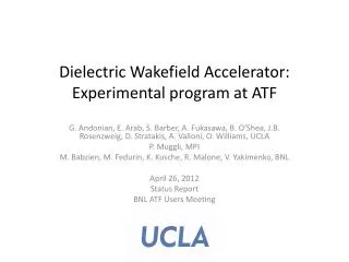
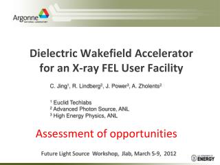
Dielectric Wakefield Accelerator for an X-ray FEL User Facility C. Jing1, R. Lindberg2, J. Power3, A. Zholents2 1 Euclid Techlabs 2 Advanced Photon Source, ANL 3 High Energy Physics, ANL Assessment of opportunities Future Light Source Workshop, Jlab, March 5-9, 2012
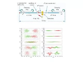
Multi-user soft x-ray FEL facility based on SRF linac (talk by J. Corlett) ~ 250 m ~ 100 m ~ 50 m ~ 350 m 40 MeV 2.4 GeV Bunch compressor Spreader ~ 50 m Energy gain 13 MeV/m
Motivation • Reduce construction and operational costs of a high bunch rep. rate FEL facility: • accelerating gradient > 100 MV/m, • peak current > 1KA, • bunch rep. rate of the order of 1MHz, • electron beam energy of a few GeV
Dielectric Wakefield Accelerator • Simple geometry • Capable to high gradients • Easy dipole mode damping • Tunable • Non expensive Recent impressive results (obtained along development of a Linear Collider): - 1000 MV/m level in the THz domain (UCLA/SLAC group) - 100 MV/m level in the MHz domain (AWA/ANL group)
Wake field in dielectric tube induced by a short Gaussian beam e Q 2a 2b Cu a=240 um; Q=1 nC; bunch length=0.5 ps (FWHM), f=650 GHz
+ r (z) W - W z d d d Road map to a high energy gain acceleration Increase Transformer Ratio, i.e., a ratio of the maximum energy gain experienced by witness bunch to maximum energy loss experienced by drive bunch or train of bunches. Beam based RB, RBT Structure based two channels Ramped Bunch Reference: Bane et. al., IEEE Trans. Nucl. Sci. NS-32, 3524 (1985) Ramped Bunch Train Reference: Schutt et. al., Nor Ambred, Armenia, (1989)
Euclid Quartz DWA (before metalization) ID=400 um A schematic of a x-ray FEL user facility based on a 2.4 GeV DWA FEL10 FEL2 FEL1 1 MHz, P=320 kW
Key technology: bunch shaping enhances transformer ratio Triangular bunch TR~10 Double triangular bunch TR~17
TM110 TM010 TM010 Deflecting cavity Double EEX technique: a convenient tool for bunch shaping Emittance exchange Emittance exchange FODO -I -I -I -I T B B QD QD QF QF B B B B QF QF QD QD QD QD QF QF B B QD QF QD QF x → z emit. exch. z →x emit. exch. Bunch shaping manipulations Mask Low charge witness (main) bunch can also be made out of drive bunch at the same time
Thermal load and cooling The structure overheating problem is much less severe in the DWA comparing to S-band Cu linac because of a small amount of energy used to excite the wake fields and a short period of time that the wake field remains inside of the structure. Average power load 50 W/cm2 at a 100 kHz rep. rate mostly dissipates in Cu The pulse temperature rise from the wake field pulse is estimated to be only ~ 20 ºC
Beam loading 10 MeV in 10 cm 150 KeV (~1.5%)
Electron bunch is strongly chirped in energy Accelerated current Wakefield
Strongly chirped beams for FEL applications: preliminary results • For short beams (<10 um rms) the energy chirp is approximately linear in time • Accelerated beam is strongly chirped (little FEL gain) • Using the chirp to compress the beam does not seem to be useful for radiation (although it is at the limit of various typical FEL approximations) • Tapering of undulator strength or period can counteract large energy chirp and maintain gain For example, chirping the undulator strength K we have Power evolution of DWA beam + undulator taper Power profile near saturation z/LG = 20 Chirped SASE spectrum near saturation z/LG = 20 Nonlinear regime Linear gain Some applications favors wide bandwidth
Summary • Several DWAs driven by a single SRF linac can be used to serve several FEL undulator lines, each at a 100 kHz rep. rate. • Energy chirped electron bunch coming from DWA will produce a powerful broad band x-ray light. • A proposed facility is energy efficient and may have a relatively low operational cost. • Much more studies are needed to prove the feasibility of DWA and to solicit new ideas.