Download
1 / 20
200 likes | 354 Vues
Design Challenges in PEP-X: An Option for Soft X-Ray FEL. R. Hettel for Y. Cai SLAC National Accelerator Laboratory 3 rd Low Emittance Ring Workshop July 8-10, Oxford, England. Motivation for enhanced DLSR performance. FEL. -. 10 12. Photons per pulse. DLSR. 10 6. -. -. -.

E N D
Design Challenges in PEP-X:An Option for Soft X-Ray FEL R. Hettel for Y. Cai SLAC National Accelerator Laboratory 3rd Low Emittance Ring Workshop July 8-10, Oxford, England
Motivation for enhanced DLSR performance FEL - 1012 Photons per pulse DLSR 106 - - - 100 Hz 100MHz Rep rate FELs becoming more ring-like: higher rep rate, reduced photons/pulse Can rings become more FEL-like: lower rep rate, increased ph/pulse?
Acknowledgements • FEL & BeamPhysics Department: Karl Bane, Yuantao Ding, ZhirongHuang, Alexander Novokhatski, Lanfa Wang • SSRL: Xiaobiao Huang, James Safranek, John Schmerge • Accelerator Design Department: Yuri Nosochkov, Min-Huey Wang • Advance Computing Department: Cho-Kuen Ng, Liling Xiao • SLAC Senior Management: Jerome Hastings, Robert Hettel, Norbert Holtkamp, Chi-Chang Kao
PEP-X DLSR (“PEP-Hex”) • Diffraction limited ring for 1.5 Å (e=l/4p = 12 pm) • Good beam lifetime 3 hours • Good injection with 10 mm acceptance • Achievable machine tolerances 20 microns • Off-axis injection E = 4.5 GeVI = 200 mA ex,y = 12/12 pm-rad 54 7BA cells off-axis injection Y. Cai, K. Bane, R. Hettel, Y. Nosochkov, M-H. Wang, M. Borland, Phys. Rev. ST Accel. Beams 15, 054002 (2012)
[Note: most recent version of PEP-X is 6-GeV PEP-X (“PEP-Xtra”)] • Convert PEP-II hexagonal tunnel to circular geometry • 7BA lattice (72 cells), 5-m straight sections • 48 ea 5-m straights available for IDs; 17600 m2 hall needed for 16 beam lines; east and west arcs not practical for beam lines • 120-m straights available for injection and bypass options • Cost of larger ring offset by reduced cost for experimental halls E = 6 GeV I = 200 mA ex,y = 5/5 pm-rad 72 7BA cells off-axis injection
PEP-X achromats (Developed from MAX-IV design) • ~ 3 ~ C-3 • = dipole bend angle • C = ring circumference • = 29 pm at 4.5 GeV • (no damping wigglers) Cell phase advances: mx=(2+1/8) x 3600, my=(1+1/8) x 3600. Good dynamic aperture reached by cancelation of 3rd- and 4th- order lattice resonances
Brightness and Coherence of Future Rings M. Borland for BESAC Meeting, July 2013 • DLSR Designs • Competitive pressure drives optimization • Upgrades & greenfield facilities possible • 2-3 orders of magnitude improved brightness over existing rings DLSR Science complements FELs, offering • Similar high transverse coherence • Long pulses with high repetition rate • High average / low peak power • High stability • High capacity Overseas Projects & Plans US Projects Current US Rings Legend: 0.2km/2GeV: ALS-II, 52 pm 0.8km/3GeV: NSLS-III, 30 pm 1.1km/6GeV: APS-II, 80 pm 2.2km/6GeV: PEP-X, 5 pm 6.2km/9GeV: tauUSR, 3 pm US Projects Overseas Projects & Plans Current US Rings
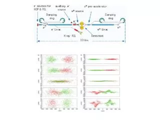
FEL lasing in a long switched bypass Pellegrini et al., 1992 Bunch switched into FEL bypass (10-100 kHz) Electron bunch is recycled for 3 damping times in ring after lasing in the bypass
Reduce bunch length from 10 ps to 1 ps without reducing bunch current Calculation of microwave instability threshold An illustration using 4.5-GeV PEP-X nominal parameters: frf = 476 MHz, Vrf=8.3 MV, frev= 136.312 kHz, sz=3 mm, Ib=0.067 mA.
* Limited by SRF HOMs ** 2- or 3-frequency RF to provide long and short bunches is possible
Transverse Gradient Undulator (TGU) Generate a linear x-dependence of the undulator fields: For a large energy-spread beam, disperse the beam according to its energy: Choose dispersion and transverse gradient: Betatron beam size << dispersed beam size rotate TGU to take advantage of very small vertically coupled emittance in DLSR low gain FEL: T. Smith et. al., J. Appl. Phys. 50, 4580 (1979). N. Kroll et. al., IEEE Journal of Quan. Electro. QE-17, 1496 (1981). high gain FEL applying to laser-plasma driven accelerator: Z. Huang, Y. Ding and C. Schroeder, Phys. Rev. Lett. 109, 204801 (2012).
IBS growth for 1ps bunch Energy Spread Horizontal Emittance Flat beam option. Vertical emittance is 1% of the horizontal one.
Electron beam and radiation size Almost round beam Dispersion dominated size Emittance size Energy spread along the undulator sE/0.511 [MeV] FEL radiation far-field pattern, (Full transverse coherence!) DsE/E=5.5x10-5 Simulation using a modified Genesis
Radiation power and spectrum @100m Saturation is reached with > 200 MW FEL power For a bunch with sz=1ps, FEL pulse energy is estimated about 0.2 mJ (~2x10¹²ph/pulse) @100m
PEP-X(FEL) at 1.5nm Note that nb is number of bunches. Bunches are recycled after three damping times in PEP-X.
SCRF in 12 GeV CEBAF Upgrade 7-cell SCRF Performance of SCRF (1497 MHz at 2 K) We assume 20 MV/m for accelerating gradient. Three modules are necessary to reach 1ps bunch length. 8 cavities in a cryomodule produce 108 MV
Multi-bunch instability driven by 24 JLab SCRF cavities =18µs =7µs =76µs Horizontal Vertical • Beam current: 200mA • Bunch Number: 3492 • Beam filling pattern: uniform • Beam Energy: 4.5GeV 200 bunches with 20mA beam current seems stable based on the current SCRF technology. That provides us 20 kHz repetition rate for the FEL.
R&D plan • 1ps bunch • Improve design of a 1.5 GHz SCRF cavity similar to those built for CEBAF upgrade • Build a prototype to demonstrate its performance in terms of accelerating gradient and sufficient damping of HOM • Install the prototype in SPEAR3 to further quantify its performance with electron beam • Study how to drive an x-oscillator • TGU in low-gain region with 20A peak current • 10,000 bunches to reach 1MHz repetition rate • Increase beam energy to 6 GeV (PEP-Xtra) and further reduce emitttance (5/5 pm) or use harmonic lasing
Conclusion • DLSRs are capable to drive SASE FEL in soft x-ray region to saturation within 100 meter using 1ps bunch in transverse gradient undulators. • Based on the CEBAF upgrade, three cryomodules with 300 MV accelerating gradient are sufficient to reduce bunch length to 1ps and retain stability of 200 bunches with 20 mA beam current. • TGU can be applied to accommodate large energy spread in storage rings. It is necessary to rotate the undulator 900, taking advantage of a very small vertical emittancein the ring. • A feasible SASE FEL at radiation wavelength of 1.5 nm • Achieves full transverse coherence • Provides 0.2-mJ energy or 2x10¹² photons per pulse • Has pulse length of 1ps • Reaches a repetition rate of 10 kHz • DLSR-based hard X-ray XFELOs might be possible (under study)