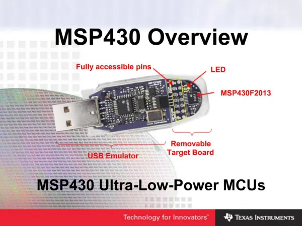
A MSP430 Microcontroller with Custom Peripherals
A MSP430 Microcontroller with Custom Peripherals. Alicia Klinefelter Dept. of Electrical Engineering, University of Virginia May 08, 2012. Context. [1]. Wireless body sensor nodes (BSN) often have microcontroller for processing Requires coding in custom ISA or assembly on finished chip

A MSP430 Microcontroller with Custom Peripherals
E N D
Presentation Transcript
A MSP430 Microcontroller with Custom Peripherals Alicia Klinefelter Dept. of Electrical Engineering, University of Virginia May 08, 2012
Context [1] • Wireless body sensor nodes (BSN) often have microcontroller for processing • Requires coding in custom ISA or assembly on finished chip • For flexible design available to C-level programmers, the MSP430 is ideal • Problem: Accelerators not addressable! [2]
Method • Explore MSP430 RTL (from OpenCores), become familiar with peripherals template, and simulate behavioral code in ModelSima • Add new peripheral block (use existing RTL), verify in ModelSima • Learn UPF format and how to incorporate the file within the synthesis flow a • Do a first-pass synthesis of the RTL not including UPF to determine power numbers a • Complete simulations of original RTL to determine functionality and power a • Complete synthesis of RTL using UPF and complete simulations to determine functionality and power r
Architecture [2] • The most important file to edit is openMSP430_defines.v for setup information • The peripheral address space is assumed to be 512B. • There are limitations to what peripherals (that are provided) can be used based on whether you plan to synthesize this for an FPGA or as an ASIC. • Program and data memory are separate (can both be RAMs) • Within the openMSP430 directory taken from OpenCores, there is a "/trunk/core/sim" directory for running behavioral simulations for all core instructions plus other test features such as debugging, clocking, and peripherals. • Run on Linux • Download Icarus Verilog and GTK Wave Viewer
Custom Peripheral • Designware divider: DW_div • Made extra peripheral addressable to MSP430 • To do behavior simulations (in ModelSim, for example), you need to also include two files within your Verilog work directory for this module to reference found in $SYNOPSYS_ROOT/dw/sim_ver directory. • One ".v" file with the same name as your DesignWarecomponent • One ".inc" file with the name of your component.
Synthesis with DC: Setup • Within the MSP430 directories from OpenCores, there is a directory including tcl scripts for DC synthesis: openmsp430 --> trunk --> core --> Synopsys • Good foundation for commands in DC • The dw_foundations.sldb file needs to be accessible to the script. This file can be found at the Synopsys root directory /<current version>/libraries/syn.
Synthesis with DC: Results • DC and DFT completed for MSP430 without errors. • Assumed voltage of 1.2V and frequency of 1MHz for fast “dco_clk” and 32kHz for slow “lfxt_clk” • Used series of tcl scripts compiled from examples in class, example provided by openMSP430 directory, and commands from documentation.
Synthesis with DC: UPF Design • There is a GUI option for creating UPF files from your synthesized design called visual UPF. • Can select individual modules, put them on separate power designs, and add power switches. • This creates a UPF script to use for the rest of the flow. • Consideration: need to add switch inputs on top-level Verilog before implementing.
P&R with ICC: Power Grid • Place and route was completed in ICC and used a set of scripts from the class tutorial. • The library setup was almost identical (as in the class tutorial). There is a script titled "design_all.tcl" used as template for most of design. • Final command set was a hybrid between what was provided in the script and using the GUI to manually do things. The final script is included in the /icc/scripts directory.
P&R with ICC: Post-Route • The standard cells were than placed, the design was routed, and filler cells were added. • To view the size of the routed design, the ruler was used to see that it is ~350umx350um • GDS and final netlist exported • Problems: Violated min density % for metal layers not used, but ignored the DRC warnings.
P&R with ICC: Visual Mode • There is a visual mode to view different design qualities. • Within the GUI, you can go to View --> Visual Mode to see the options. Cell Density
P&R with ICC: Visual Mode • Peripherals and execution unit took up a lot of space! Hierarchy
P&R with ICC: Visual Mode Clock tree routing: LFXT Clock tree routing: DCO
HSPICE Simluations • SPICE netlist found using Hercules command • nettran -verilog openMSP430.v -cdl-a -cdl-s -sp-S -verilog-b1 VDD -verilog-b0 VSS -rootCell openMSP430 -sp ./saed90nm.cdl -outTypespice -outName openMSP430.sp • Problem: SPICE format, not HSPICE • .SUBCKT <subckt name> <inputs and outputs> <BODY OF BLOCK> .ENDS <subckt name> • Need an “.end” statement • Created HSPICE stimuli file for ADD instruction • v<NAME> <NAME> <GROUND REF> <TYPE OF SIGNAL> <VALUES> • Needed to run for ~30μs (long!) • Simulation took a few days
HSPICE Simluations Cont’d • Include files in netlist: • .include "/net/plato.ee.virginia.edu/users/amk5vx/synopsys/msp430/hspice/_graphical_stimuli.scs" .lib "/net/plato.ee.virginia.edu/users/amk5vx/synopsys/msp430/hspice/SAED90nm.lib" TT_12 • Add simulation type: • .TRAN 5e-9 34e-6 START=0.0 • Add node initial conditions: • Had convergence problems, wrote Perl script to extract DFF nets • .IC + V(test_si2)=0 + V(test_si3)=0 + V(test_so3)=0 ... • Make simulation run faster: • .OPTIONS RELTOL=.01 .OPTIONS GMIN=10E-9
HSPICE Sim Results • Viewed outputs using Wave View (wv) • AND simulation took a few days (only one instruction completed) • The average current was 30.8mA at 1.2V and 1MHz. This results in a power of 36.9mW.
Provided Results • Directory of files including the results. The description of each sub-directory is: • dc: Results, scripts, ref files, and original Verilog files of the design for DC synthesis. • formality: Formality of pre and post layout files. • hercules: Used for getting SPICE netlist from the results of ICC place and route. • hspice: directory containing HSPICE netlist, perl scripts for modifying SPICE netlist to turn into an HSPICE netlist, and stimuli file. • icc: Files and scripts used for place and route. • Other loose files in the directory • The data sheet for the DesignWare divider that is being used (dw_div.pdf) • The "syn_setup" file that needs to be sourced before using all of the tools described above.
Future Work • Adding DesignWare or custom memories for the program and data memories. The difficulty isn't adding them so much as using them to feed data to the MSP430 including all of the scanning data into them and timing. • More simulations of other instructions would be good to truly know functionality across the instruction set. • Implementing power gating into the layout using UPF.
References • Fan Zhang; Yanqing Zhang; Silver, J.; Shakhsheer, Y.; Nagaraju, M.; Klinefelter, A.; Pandey, J.; Boley, J.; Carlson, E.; Shrivastava, A.; Otis, B.; Calhoun, B.; , "A batteryless 19μW MICS/ISM-band energy harvesting body area sensor node SoC," Solid-State Circuits Conference Digest of Technical Papers (ISSCC), 2012 IEEE International , vol., no., pp.298-300, 19-23 Feb. 2012. • http://opencores.com/project,openmsp430