Download
1 / 43
900 likes | 2.27k Vues
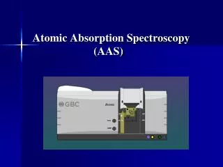
C hapter 3 Atomic Absorption Spectroscopy. 3.1. Theoretical Concepts 3.2. Atomic Absorption Instrumentation 3.3. Graphite Furnace Atomic Absorption 3.4. Control of Analytical Interferences. 3.1. Theoretical Concepts. The Atomic Absorption Process Theoretical Concepts

E N D
Chapter 3 Atomic Absorption Spectroscopy 3.1. Theoretical Concepts 3.2. Atomic Absorption Instrumentation 3.3. Graphite Furnace Atomic Absorption 3.4. Control of Analytical Interferences
3.1. Theoretical Concepts • The Atomic Absorption Process • Theoretical Concepts • Quantitative Analysis • Characteristic Concentration • Detection Limits
Fig3-2 Grotrian diagrams for K Fig 3-3Grotrian diagrams for Na
2. Theoretical Concepts⑴Integral Formula of AASFig 3-4 Typical Shape of A Atomic Absorption line
Integral Absorption FormulaBy atomic theory (3.1) By Line Shape Function ( the Nature distribute ) (3.2) The Peak Absorption Coefficient k0 is: (3.3)
⑵ Peak Absorption Theoryby Lambert-Beer’s Law: (3.4) (3.5) (3.6)
The Absorbance is: (3.7)
When: va>> ve, and v0a= v0e, then kv≈k0,
(3.9) (3.10)
3. Quantitative Analysis (3.10)
5. Detection Limit (3.12)
Hollow Cathode Lamp Emission Process Fig 3-14
4. Control of Analytical Interferences Ionization interference Matrix interference Chemical interference Background interference
Ionization Interference Ba → Ba+ + e- K → K+ + e-
(4.13) AHCL= Aa+ Ab (4.14) AD2=Ab, (4.15) Aa = AHCL- AD2
3.3. Graphite Furnace Atomic Absorption • Graphite furnace atomizer components • The Graphite Furnace Power Supply and Programmer • Quantitative analysis GFAAS • Effect of Matrix on Height and Area
1. Graphite furnace atomizer components The Graphite Furnace Atomizer A basic graphite furnace atomizer is comprised of the following components: · graphite tube · electrical contacts · enclosed water cooled housing · inert purge gas controls
THGA graphite tube Fig 4-27
The Graphite Furnace Power Supply and Programmer • A Graphite Furnace Temperature Program • Drying • Pyrolysis • Cool Down(optional) • Atomization • Clean Out • Cool Down