StormCAD Basics
StormCAD Basics. Mal Sharkey. Be Conf. 2007. Our users design, build, and operate the world’s infrastructure – improving quality of life for everyone. We provide software to help them do it better and faster. Part 1. Intro to StormCAD. What is a Storm Sewer System?.


StormCAD Basics
E N D
Presentation Transcript
StormCAD Basics Mal Sharkey
Be Conf. 2007 Our users design, build, and operate the world’s infrastructure – improving quality of life for everyone. We provide software to help them do it better and faster.
Part 1 • Intro to StormCAD
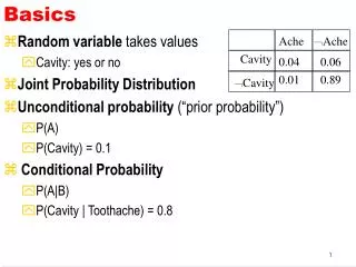
What is a Storm Sewer System? A storm sewer system is composed of surface components (e.g., gutters and inlets) and subsurface components (e.g., pipes, manholes, inlet boxes)
Storm Sewer Design • Storm sewer design and analysis consists of 2 basic parts: • Surface flow calculations • Subsurface flow calculations • Surface flow calcs evaluate the capacity of gutters (i.e., gutter spread and depth) and inlets (for inlets on grade, part of the flow, called “bypass flow,” will not be picked up and will continue down to the next inlet). • Subsurface flow calcs evaluate the capacity of the subsurface pipes to prevent flooding. Storm sewer pipes should always point downhill, and the systems are branched (i.e., typically, there should not be loops).
Storm Sewer Design Subsurface (pipe) layout Surface (gutter) connectivity Plan View Profile View
Gutters • Flow typically travels to storm sewer inlets though gutters • The engineer is interested in the width and depth of the gutter flow, and has to make sure that neither is excessive. • Gutter flow is analyzed using a form of Manning’s equation
Inlets • Three common inlet types are grate inlets, curb inlets, and combination inlets. • Inlets may be located on a continuous grade or in a sag location • Inlets on grade do not intercept 100% of the flow that comes to them—some of the flow bypasses and goes to the next inlet downgrade • HEC-22 calculation methods are used to determine gutter spread and depth and inlet capacity
StormCAD Storm sewer design & analysis with inlet modeling
StormCAD Applies to: • Commercial site design • Land development • Roadway drainage design • Planning, mapping, and inventories for larger areas (e.g., municipality)
StormCAD Capabilities • Uses rational method hydrology • Performs gradually varied flow profile analysis • Incorporates HEC-22 methods for inlet and gutter capacity calcs, including gutter spread and bypass flow calcs • Performs automated pipe & inlet design • Includes GIS and database connections • Generates profile plots and tabular reports • Includes MicroStation & AutoCAD integration options • Includes Scenario Management
User Interface Zoom Tools Tabular Reports Graphical Tools Compute Button Scenario Element Symbology Drawing Area Layout Tools Background Layers
Basic Data Entry Layout Toolbar Property Grid Pipe Tool Right-click menu to change element type FlexTables • Sort • Filter • Global Edit • Customize
ModelBuilder: Using External Data Convert CAD lines, polylines, and blocks Connect to any database & keep it in sync with your model Connect to shapefiles
Part 2 • Getting familiar with StormCAD
Gutter A little more theory…Open Channel Flow • Open channel flow is flow that has a free water surface open to the atmosphere. • It occurs in natural rivers and streams, manmade ditches and channels, gutters, and gravity-flow pipes.
Conservation of Energy • In open channel flow, the pressure head term (p/γ) is replaced by the vertical flow depth y • The energy equation between sections 1 and 2 for the channel shown is written as:
Open Channel Flow Definitions Normal Flow • If a channel shape remains constant for a long enough distance, the flow will reach a constant “normal depth.” Varied Flow • Flow depth typically varies along the length of a channel due to factors like changing channel shape or flow depths other than normal depth on the upstream or downstream end. • Varied flow can change gradually along a channel (“gradually varied flow” or GVF) or rapidly (in the case of a hydraulic jump). Supercritical vs. Subcritical Flow • These are the 2 basic flow types possible for flow in an open channel. • Supercritical flow is shallow, high-velocity flow • Subcritical flow is deeper, slower-velocity flow • Flow can transition from subcritical to supercritical flow, or vice versa • Between supercritical flow and subcritical flow is the “critical depth.” This value can be determined for any channel and used to classify the flow type. Sometimes, it is also used as a starting point (boundary condition) in GVF calculations
Open Channel Flow Types Normal Flow Transition from Subcritical to Supercritical flow Transition from Supercritical to Subcritical Flow (Hydraulic Jump)
Graphic Output Annotation Color Coding Profiles
Data Management Queries Network Navigator Selection Sets
Part 3 • Analysis in StormCAD
Rational Method To compute a peak flow rate from a watershed, a method such as the Rational Method can be used: Q = c × i × A • Q is the peak discharge from the drainage area • c is the “runoff coefficient” (the fraction of rainfall that is converted to runoff) • i is the intensity of the rainfall for a design storm event having a duration equal to the drainage area “time of concentration”. This can be obtained using intensity-duration-frequency curves for the locale (see below). • A is the area
Inlet Calculations Perform inlet capture & bypass calcs using HEC-22 methods Store inlet properties in an engineering library Set up gutter networks
Multiple Scenarios Create alternative input data sets with Alternative Manager Model a variety of situations using Scenario Manager
Active Topology Before site is developed (proposed elements are inactive) After site is developed
Viewing Output FlexTables Reports Property Grid
MicroStation & AutoCAD Integration StormCAD can run inside MicroStation or AutoCAD
StormCAD Basics Mal Sharkey