Download
1 / 5
50 likes | 591 Vues
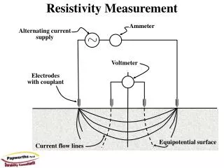
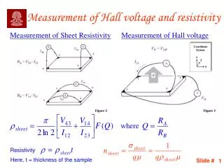
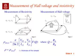
Measurement of Hall voltage and resistivity. Measurement of Resistivity. Measurement of Hall voltage. where. t = thickness of the sample. Variation of F with Q. F(Q) = 1, if R A = R B.

E N D
Measurement of Hall voltage and resistivity Measurement of Resistivity Measurement of Hall voltage where t = thickness of the sample
Variation of F with Q F(Q) = 1, if RA = RB
For Hall measurements the magnitude of the magnetic field should be small to avoid magneto-resistance or reduction in conductance due to the magnetic field Measurement of both mobility and sheet charge density is possible The volume density of carriers is possible if the thickness of the sample is known The sign of the charge carriers can be found from the sign of the Hall voltage Advantageous for samples having 2DEG since direct measurement of sheet charge density can be made unlike CV technique Hall measurement includes overall effects of both majority and minority carriers Summary of the Hall measurement
The Hall factor which depends on the scattering mechanisms The Hall mobility is related to the conductivity mobility as The contacts should be ohmic The contact sizes should be as small as possible w.r.t. the distance between them (see Van der Pauw paper) A special cloverleaf geometry is used for accurate measurements which is relatively unaffected by the size of the contacts Multiple conduction paths, if present, will lead to errors in mobility estimates Sources of inaccuracies Special geometry to reduce the effect of the contact size
Types of mobilities • Conductivity mobility This mobility relates current density to the electric field and is given as: • Drift mobility This mobility directly relates the carrier velocity to the electric field and is given as: • MISFET and field-effect mobility: This is measured in a MOSFET device using either transconductance or drain conductance. • Hall mobility: Measured from Hall measurement by application of magnetic field