Download
1 / 12
140 likes | 387 Vues
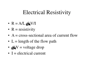
Earth and Resistivity Testers. C.A 6460 & C.A 6462. SALES PRODUCT INFORMATION Electrical Testing and Safety Cécile Le Goué. Mains characteristics. 4 Resistance (automatic range selection) 4 Measurement frequency : 128 Hz 4 Open circuit voltage : £ 42V peak

E N D
Earth and Resistivity Testers • C.A 6460 & C.A 6462 SALES PRODUCT INFORMATION Electrical Testing and Safety Cécile Le Goué
Mains characteristics • 4 Resistance (automatic range selection) • 4 Measurement frequency : 128 Hz • 4 Open circuit voltage : £ 42V peak • 4 Voltage detection from 20 to 250V AC (between H &E or E&S) • 4 Auxiliary rodresistance: • Voltage circuit resistance : max 50kW • Current circuit resistance : max 50kW Measurement range Resolution Test current Accuracy Open circuit voltage W W £ 10 mA ± 2%R + 1 ct 0,00…19,99 0,01 42 V peak W W £ 1 mA ± 2%R + 1 ct 20,0…199,9 0,1 42 V peak W W £ 0,1 mA ± 2%R + 3 cts 200…1999 1 42 V peak
A special built-for-field design Very robust case, waterproof IP67 closed et IP53 opened A folding handle A folding cover
A complete front panel... C.A 6462: Mains supply socket with dust cover and charge indicator Large backlit LCD display Fuse holder 4 connecting terminals and capture bar Momentary-control push-button 3 lights indicate events liable to impair results
Strengths : Captive bar between S and ES for switching easily from 4-wire to 3-wire measurement method easy connection : terminals are colour-coded and correspond to the colour-coded accessory leads Rechargeable NiMH battery with internal charger (only C.A 6462) • On-site case with cover for use in difficult conditions • Large backlit LCD display constantly lit for good readability as well as legibility • 3 indicators for measurement liability. • Automatic selection of the measurement range and current for maximum accuracy.
Applications • "4-rod" resistivity measurement • "3-rod" earth measurement : 62% method • "3-rod" earth measurement : triangle method • "4-rod" earth measurement : 62% or triangle methods • "4-rod" coupling measurement
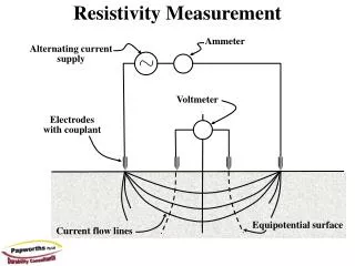
"4-rod" resistivity measurement : Wenner method Goal : To choose the best location and shape of earthing rods and networks, before they are put in place. Method : to place the 4 spikes in line and equidistant from the distance a. The soil resistivity (W.m) at the depth h(3/4a) is : 2 a R R is the resistance read on the instrument
"3-rod" earth measurement : 62% method Goal: check the existing earth resistance value Method : place the 2 auxiliary rods in line with existing earth rod so that : DE-S = 62% DE-H To validate the measurement, move the S rod at + 10% and - 10% : - if the result does not vary, the measurement is correct - if not, repeat measurements while increasing distances E-H and E-S.
"3-rod" earth measurement : triangle method Goal : check the existing earth resistance value RE This method is used when it's not possible to place the rods in line : Place E, S and H in equilateral triangle. To validate the measurement, move the S rod from one side to the other one : - if the result does not vary, the measurement is correct - if not, repeat measurements while increasing distances.
"4-rod" earth measurement : 62% or triangle methods Goal : check the existing earth resistance value RE Method : - connect E and ES with the earth to be measured - place the 2 others auxiliary rods so that : DE-S = 62% DE-H or in equilateral triangle. Follow the same validation procedure as for "3-rod" methods. The advantage of the 4-rods method is that frees itself from the resistance of the E(x) connected cords.
"4-rod" coupling measurement Goal : to test the influence of one earth on another in the event, for example of lightning Method : - measure Rm and Rn with the 62% method - measure Rmn with the "4-wire" method explained opposite The coupling coefficient is : k = Rcoupling / Rm with Rcoupling = (Rm + Rn - Rmn ) / 2 EDF recommends k < 0.15
TO ORDER Earth and resistivity tester C.A 6460 P01.1265.01 delivered with batteries and user's manual in 5 languages Earth and resistivity tester C.A 6462 P01.1265.02 delivered with a 2m European-type mains supply lead and a user's manual in 5 languages Replacements parts : European mains lead P01.2951.74 NiMH 9.6V/3.5AH storage battery P01.2960.21 HPC 0.1A fuses (pack of 10) P01.2970.12 1.5V alkaline LR14 battery (pack of 2) P01.2960.27 Accessories : STANDARD Earth / Resistivity kit P01.1018.23 PRESTIGE Earth / Resistivity kit P01.1018.25