Download
1 / 44
470 likes | 865 Vues
Integrated Coastal Zone Management - Coastal Hazard Line Mapping By M Dharma Raj Addl. S.G , SZ & ICZM Project Director Survey of India. Coastal Hazard Line demarcation & Integrated Coastal Zone Management Based on established scientific principles.

E N D
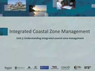
Integrated Coastal Zone Management - Coastal Hazard Line Mapping By M Dharma Raj Addl. S.G , SZ & ICZM Project Director Survey of India
Coastal Hazard Line demarcation & • Integrated Coastal Zone Management Based on established scientific principles Aim of the project
Demarcation of a Vulnerability Setback / Hazard line. • Setback line is the boundary line beyond which the effect of Natural Hazards such as erosion and sea-level-rise will not be felt. • The parameters involved are: Elevation, sea-level-rise & Coastal Erosion. ROLE OF SOI
Elevation: DEM will be generated by Photogrammetry. • Sea-Level Rise:Tidal data will be processed to compute the 100 year Return Period Extreme Tidal Height values at any Transect point using Weibull Distribution and Linear Interpolation. • Coastal Erosion:Annual Rate of Coastal Erosion will be Computed by comparing the oldest Topo-Map and the Latest Aerial Photography Ortho / satellite Image and extrapolated to next 100 years.
Fresh Aerial Photography” with 9 cm gsd using Digital Aerial Camera. • Primary Ground Control. • Block Control • Control extension - Photogrammetry. • AT & Block adjustment. • DEM Collection at 5m Grid. • Ortho & Feature Collection ElevAtion Data
Use extreme elevation data of 100 year return period at 20 major and 250 minor ports computed by G & RB, SOI. • Interpolate at other Transect points using linear interpolation. • Transfer these heights to the DEM and join the line. • This will give the flood line. Sea Level Rise
Compute rate of coastal erosion at every 500 m transect point using old Topo Sheet and new satellite image / ortho photo data. • Extrapolate for 100 year return interval using linear extrapolation. • This line represents coastal erosion line. Coastal Erosion
The final Hazard Line Is the most landward of the Flood Line & Erosion Line. • Delineate the same In a GIS Environment. • Mark on Ground with pillars / markers. Hazard Line
Hazard Line HAZARD LINE EROSION LINE Max Flood line Land SEA AREA
Project Tasks • Levelling • Establish BMs & BCP (heights) • b) Establishment of Primary GCPs • c)Establishment of Secondary GCP and BCP (Horizontzl) • Aerial Photography • QA/QC procedures • Photography • Statutory clearances • Photogrammetry and Map Data generation • Aerial Triangulation (AT) • Digital Elevation Model (DEM) and Contour generation • Ortho-rectification
Tidal Data Analysis • Computation of 100 year Return Period Flood Line. • Erosion Data Analysis • Computation of 100 year Return Period Erosion Line. • Mapping the final Hazard Line • Most Landward of Flood Line / Erosion Line. • Demarcation of Hazard Line • Fixing of Markers/ Pillars
Aerial Photography & Preliminary AT/DEM/Ortho. • Rigorous Photogrammetric Survey. • Quality Control at various stages. Tasks to be outsourced
Provision of Ground Control Points By Survey of India
Levelling –Establishment of Bench Marks for Height • High Precision • Double Tertiary • Single Tertiary • Stability Check • Linear Adjustment • Along The Flight Line • Post pointing of Staff Positions to serve as Check Points.
Principle of Whole To Part • Leap Frog Method • Least Square Adjustment Carrier Phase • Relative Positioning (Phase Difference) • Static Mode • Loop Closure • Positional Accuracy 2 Cm
BCPs Aerial Triangulation • Radial Line Method • Loop Closure Check • Positional Accuracy 4 Cm • Planning • Adjustment • DEM Mass Points DEM • Density of Mass Point@ 5 m • Omission of Break lines • Checking of TIN
AERIAL PHOTOGRAPHY • Most vital component of this Project. • Photography is just a means to the end. • Its specifications have been designed to meet the end-product • gsd 9 cm • Designed to maximize its utility in Photogrammetric Processes
Specifications for Aerial Photography • Acquisition Requirements • Platform • Camera • Mounts • Certification • Flight Plan and Coverage ( http://www.moef.nic.in) • Flying Conditions • Image Requirements • Spatial Resolution • Spectral Resolution • Radiometric Resolution • Control Requirements • Pre-pointed Control • Differential GPS/GNSS & IMU Control • Ground Stations • GPS Control for horizontal control (1st Order) • Levelling Heights for vertical control (H.P BMs)
QC embedded in Work flow • Closely Managed Processes with built-in Quality Checks • Documentation • Standard Operation Procedures • Work Flows • Quality Checks at each stage • GCP Control (Plan & Height) – Rigorous Deptt. standards • Flight Planning - Approval • Flight Execution & Monitoring (Differential GPS and IMU) • Flight Evaluation – Corrective action while resources still at site • Go ahead approval. • Quality Control Records
Preliminary AT/Ortho-rectification (FULL PROOF QA/QC )with minimum effort and gestation lag) • Suitability for Photogrammetric Processes, • check for Direct Sensor Orientation, • Pre-pointed controls, • overlaps & gaps • Measurement and certification of work also based on Preliminary Ortho FULL PROOF QC
Flood Line Mapping Input • 100 year return period elevations of 20 primary ports. • Data of about 250 secondary ports. • 0.5m contours / DEM. • Ortho aerial image.
Interpolation Of Return Period Tidal Elevations • Compute 100 year Return Period Max Elevations values at each of the 20 primary ports. • Compute 100 year Return Period values at each of the 250 Secondary Port using 2 neighboring primary ports • This will give 100 year RPs at about every 30 km. • Draw a base line for measurements and make Transects at every 500 m. • Linearly Interpolate at Transect points using 2 neighboring Primary / Secondary ports.
Interpolation Of Return Period Primary Ports Secondary Ports Transect Points
Tidal Data Analysis • Survey of India is one of the premier organizations in the world having more than 130 years of expertise in tidal data acquisition. • It is a large store house of tidal data , collected from major part of its area of responsibility. • Presently Survey of India is maintaining a huge network of permanent tidal stations , located along the Indian Coast and Islands. • These tidal stations are equipped with state-of-the-art digital tide gauges , co-located with dual frequency GPS receivers and real time data transmission facilities through dedicated VSAT network.
Determination of Tidal Heights for 100 yrs return period • Estimated tidal heights for 100 years return period have been determined for the ports having tidal records for at least 10 years. 20 such tidal stations have been identified in the east and west coast for determining the tidal level for 100 years return period. Methodology Provide minimum 10 years of historical tide gauge data for all ports within the state boundary for which long term observations are available. Determine the Annual Maximum Water Level for each year and each port. Reduce Annual Maxima from Chart Datum to IMSL and tabulate. Rank order the data Calculate Weibull distribution and plotting positions of all the available data. Fit regression line to plotted data and extrapolate to 100 years. Calculate the tidal heights for 100 years return period.
Interpolation Of Return Period At Minor Ports • 100 years Return Period for major port M1 (Known Station) = 5.89 m • 100 years Return Period for major port M2 (known Station) = 4.80 m • Distance between M1 & M2 = 47.52 km • Distance between M1 and Secondary port S = 21.46 km • Indirect Interpolation: • Tidal Ht. for 100 year RP-HAT of M1 =5.8900-4.5051 = 1.3849 • Tidal Ht. for 100 year RP-HAT of M2 =4.8000-4.0379 = 0.7621 • Correction for S = 1.3849+ {(0.7621-1.3849)*Distance from M1 (21.46)}/Total Distance(47.52) =1.1036 m 100 years Return Period for S = HAT of S + Correction = 4.2351+1.1036 = 5.3387 m • 100 years Return Period Calculated by Indirect interpolation = 5.3387 m
DIFFERENCE IN RP-HAT = 0.6228 m RP - HAT = 1.3849 m 5.89 m 4.80m HAT = 4.5051 m RP - HAT = 0.7621 M 47.52 km HAT = 4.0379 m
Completeness of Tidal Data ….. • All available Data up to 2010 will be used after checking for quality. • Month-wise distribution / availability of data will be checked. • Regularity of Missing Data will also be checked. • Tsunami / Cyclone data will also be included.
HEIGHT OF TIDE ABOVE IMSL INDIAN MEAN SEA LEVEL (IMSL) HEIGHT OF TIDE ABOVE CD CHART DATUM (CD)
Linear Interpolation at Transect Points Two ports ( primary / secondary) will be taken at a time: (x,y) (x2,y2) (y - y1) Δy ( x1,y1) (x-x1) Δx (y - y1) / (x-x1) = (Δy/ Δx) Based on Equation of line or Similar Triangles y = y1 + (Δy/ Δx)(x-x1)
Erosion Line Mapping. Required inputs:- Multiple shoreline positions- User-generated baseline
Transects For Erosion Line Mapping. DSAS generates transects that are cast perpendicular to the baseline at a user-specified spacing alongshore.The transect/shoreline intersections along this baseline are then used to calculate the rate-of-change statistics.