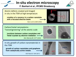
Analytical Transmissions Electron Microscopy (TEM)
Analytical Transmissions Electron Microscopy (TEM). Part I: Basic principles Operational modes Diffraction Part II: Imaging Sample preparation Part III Spectroscopy. Imaging and contrast. Resolution of the eyes:~ 0.1-0.2 mm Resolution in a visible light microscope: ~300 nm.


Analytical Transmissions Electron Microscopy (TEM)
E N D
Presentation Transcript
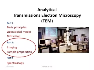
Analytical Transmissions Electron Microscopy (TEM) Part I: Basic principles Operational modes Diffraction Part II: Imaging Sample preparation Part III Spectroscopy MENA3100 V13
Imaging and contrast Resolution of the eyes:~ 0.1-0.2 mm Resolution in a visible light microscope: ~300 nm Modern TEMs with Cs correctors have sub Å resolution!
BiFeO3 Pt TiO2 Glue SiO2 Si 200 nm Imaging / microscopy TEM - High resolution (HREM) - Bright field (BF) - Dark field (DF) - Shadow imaging (SAD+DF+BF) STEM - Z-contrast (HAADF) - Elemental mapping (EDS and EELS) GIF - Energy filtering Holography MENA3100 V08
Contrast • Difference in intensity of to adjacent areas: The eyes can not see intensity chanes that is less then 5-10%, however, contrast in images can be enhanced digitally. NB! It is correct to talk about strong and week contrast but not bright and dark contrast
Amplitude contrast andPhase-contrast images The elctron wave can change both its amplitude and phase as it traverses the specimen Give rise to contrast glue (light elements) hole Ag and Pb We select imaging conditions so that one of them dominates. Si
Apertures Condenser aperture Objective aperture Selected area aperture MENA3100 V13
Use of apertures Condenser aperture: Limits the number of electrons hitting the sample (reducing the intensity), Affecting the diameter of the discs in the convergent electron diffraction pattern. Selected area aperture: Allows only electrons going through an area on the sample that is limited by the SAD aperture to contribute to the diffraction pattern (SAD pattern). Objective aperture: Allows certain reflections to contribute to the image. Increases the contrast in the image. Bright field imaging (central beam, 000), Dark field imaging (one reflection, g), High resolution Images (several reflections from a zone axis). MENA3100 V13
3,8 Å 1,1 nm Simplified ray diagram Parallel incoming electron beam Si Sample Objective lense Diffraction plane (back focal plane) Objective aperture Selected area aperture Image plane MENA3100 V13
Objective aperture: Contrast enhancement Ag and Pb Si hole glue (light elements) No aperture used Central beam selected Intensity: Thickness and density dependence Mass-thickness contrast
Mass-thicknesscontrast in TEM Incoherent elastic scattering (Rutherford scattering): peaked in the forward direction, t and Z-dependent Areas of greater Z and/or t scatter electrons more strongly (in total). TEM variables that affect the contrast: -The objective aperture size . -The high tension of the TEM. Williams and Carter, TEM, Part 3 Springer 2009
Exampleofmass-thicknesscontrast in TEM mode- Metalshadowing BF-TEM image of latex particles on an amorphous C-film. The contrast is t-dependent. What is the shape of the particles? Effect of evaporation of a heavy metal (Au or Au-Pd) thin coating at an oblique angle. What is the contrast due to in the image? Effect of inversing the contrast of the image. The uneven metal shadowing increases the mass contrast and thus accentuates the topography. Williams and Carter, TEM, Part 3 Springer 2009
50 nm Objective aperture: Contrast enhancement Intensity: Dependent on grain orientation Diffraction contrast Try to make an illustration to explain why we get this enhanced contrast when only the central beam is selected by the optical aperture.
Amplitude contrast Two principall types and Diffraction contrast Mass-thickness contrast -In crystaline materials -Primary contrast source in amorphous materials -Coherent electron scattering -Incoherent electron scattering Both types of contrasts are seen in BF and DF images -Can use any scattered electrons to form DF images showing mass-thickness contrast -Two beam to get strong contrast in both BF and DF images.
Objective aperture BF image DF image HREM image Size of objective apertureBright field (BF), dark field (DF) and High resolution EM (HREM) Phase contrast Amplitude/Diffraction contrast
Weak-beam Amplitude/diffraction contrast:weak-beam (WB) Dissociation of pure screw dislocation In Ni3Al, Meng and Preston, J. Mater. Scicence, 35, p. 821-828, 2000. MENA3100 V13
Shadow imaging (diffraction mode) Parallel incoming electron beam Sample Objective lense Diffraction plane (back focal plane) Image plane
sample Obj. lens Obj. aperture BF image DF image DF image Bending contours Solberg, Jan Ketil & Hansen, Vidar (2001). Innføring i transmisjon elektronmikroskopi MENA3100 V13
Double electron diffraction leads to oscillations in the diffracted intensity with increasing thickness of the sample No double diffraction with XRD, kinematical intensities Forbidden reflection may be observed t0: Extinction thickness Periodicity of the oscillations t0=πVc/λIF(hkl)I Incident beam Wedge shaped TEM sample t0 Double diffraction, extinction thickness Doubly diffracted beam Transmitted beam Diffracted beam
g 000 Ig=1- Io t Thickness fringes/contours In the two-beam situation the intensity of the diffracted and direct beam is periodic with thickness (Ig=1- Io) e Sample (side view) Sample (top view) Hole Ig=(πt/ξg)2(sin2(πtseff)/(πtseff)2)) t = distance ”traveled” by the diffracted beam. ξg = extinction distance Positions with max Intensity in Ig MENA3100 V13
BF image DF image Thickness fringesbright and dark field images Sample Sample MENA3100 V13
HREM image 2 nm Phase contrast: HREM and Moire’ fringes Long-Wei Yin et al., Materials Letters, 52, p.187-191 A Moiré pattern is an interference pattern created, for example, when two grids are overlaid at an angle, or when they have slightly different mesh sizes (rotational and parallel Moire’ patterns). Interference pattern 200-400 kV TEMs are most commonly used for HREM http://www.mathematik.com/Moire/ MENA3100 V13
Moire’ fringe spacing Parallel Moire’ spacing dmoire’= 1 / IΔgI = 1 / Ig1-g2I = d1d2/Id1-d2I Rotational Moire’ spacing dmoire’= 1 / IΔgI = 1 / Ig1-g2I ~1/gβ = d/β Parallel and rotational Moire’ spacing dmoire’= d1d2/((d1-d2)2 + d1d2β2)0.5 g1 g2 Δg g1 Δg β g2 MENA3100 V13
SAFETY!!!! • Know what you handling. • MSDS • Protect your self and others around you. • Follow instructions • If an accident occurs, know how to respond.
Work in the Stucture Physics lab • Get the local HMS instructions from Ole Bjørn Karlsen Sign a form confirming that you have got the information Ask
What to considder before preparing a TEM specimen • Ductile/fragile • Bulk/surface/powder • Insulating/conducting • Heat resistant • Single phase/multi phase • Etc, etc……. What is the objectiv of the TEM work?
Crushing Cutting saw, “diamond” pen, ultrasonic drill, FIB Mechanical thinning Grinding, dimpling, Tripod polishing Electrochemical thinning Ion milling Coating Replica methods Etc. Specimen preparation for TEM
Self-supporting disk or grid • Self supporting disk • Consists of one material • Can be a composite • Can be handled with a tweezers • Metallic, magnetic, non-magnetic, plastic, vacuum If brittle, consider Cu washer with a slot • Grid • Several types • Different materials (Cu, Ni…) • Support brittle materials • Support small particles The grid may contribute to the EDS. 3 mm
Preparation of self-supporting discsTop view • Cutting • Ductile material or not? • Grinding • 100-200 μm thick • polish • Cut the 3mm disc • Dimple ? • Final thinning • Ion beam milling • Electropolishing
Top view Cross section TEM sample preparation: Thin films Grind down/ dimple Cut out cylinder Ione beam thinning Grind down and glue on Cu-rings Cut out a cylinder and glue it in a Cu-tube Cut out slices • Cross section Glue the interface of interest face to face together with support material or • Focused Ion Beam (FIB) Cut a slice of the cylinder and grind it down / dimple Cut off excess material Ione beam thinning MENA3100 V13