Download
1 / 52
520 likes | 978 Vues
Chapter 7 Continued Entropy: A Measure of Disorder Study Guide in PowerPoint to accompany Thermodynamics: An Engineering Approach , 5th edition by Yunus A. Çengel and Michael A. Boles. Example 7-9

E N D
Chapter 7 ContinuedEntropy: A Measure of DisorderStudy Guide in PowerPointto accompanyThermodynamics: An Engineering Approach, 5th editionby Yunus A. Çengel and Michael A. Boles
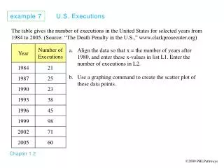
Example 7-9 Air, initially at 17oC, is compressed in an isentropic process through a pressure ratio of 8:1. Find the final temperature assuming constant specific heats and variable specific heats, and using EES. a. Constant specific heats, isentropic process For air, k = 1.4, and a pressure ratio of 8:1 means that P2/P1 = 8 b.Variable specific heat method
Using the air data from Table A-17 for T1 = (17+273) K = 290 K, Pr1 = 1.2311. Interpolating in the air table at this value of Pr2, gives T2 = 522.4 K = 249.4oC c.A second variable specific heat method. Using the air table, Table A-17, for T1 = (17+273) K = 290 K, soT1 = 1.66802 kJ/kgK. For the isentropic process
At this value of soT2, the air table gives T2 = 522.4 K= 249.4oC. This technique is based on the same information as the method shown in part b. d.Using the EES software with T in oC and P in kPa and assuming P1 = 100 kPa. s_1 = ENTROPY(Air, T=17, P=100) s_2 = s_1 T_2 = TEMPERATURE(Air, P=800, s=s_2) The solution is: s_1 = 5.668 kJ/kgK s_2 = 5.668 kJ/kgK T_2 = 249.6oC Example 7-10 Air initially at 0.1 MPa, 27oC, is compressed reversibly to a final state. (a) Find the entropy change of the air when the final state is 0.5 MPa, 227oC. (b) Find the entropy change when the final state is 0.5 MPa, 180oC. (c) Find the temperature at 0.5 MPa that makes the entropy change zero. Assume air is an ideal gas with constant specific heats.
T P2 2 a c b P1 1 s c. The T-s plot is Give an explanation for the difference in the signs for the entropy changes.
Example 7-11 Nitrogen expands isentropically in a piston cylinder device from a temperature of 500 K while its volume doubles. What is the final temperature of the nitrogen, and how much work did the nitrogen do against the piston, in kJ/kg? System: The closed piston-cylinder device
Property Relation: Ideal gas equations, constant properties Process and Process Diagram: Isentropic expansion Conservation Principles: Second law: Since we know T1 and the volume ratio, the isentropic process, s = 0, allows us to find the final temperature. Assuming constant properties, the temperatures are related by Why did the temperature decrease?
First law, closed system: Note, for the isentropic process (reversible, adiabatic); the heat transfer is zero. The conservation of energy for this closed system becomes Using the ideal gas relations, the work per unit mass is Why is the work positive?
Extra Assignment For the isentropic process Pvk = constant. Use the definition of boundary work to show that you get the same result as the last example. That is, determine the boundary work and show that you obtain the same expression as that for the polytropic boundary work. Example 7-12 A Carnot engine has 1 kg of air as the working fluid. Heat is supplied to the air at 800 K and rejected by the air at 300 K. At the beginning of the heat addition process, the pressure is 0.8 MPa and during heat addition the volume triples. (a) Calculate the net cycle work assuming air is an ideal gas with constant specific heats. (b) Calculate the amount of work done in the isentropic expansion process. (c) Calculate the entropy change during the heat rejection process. System: The Carnot engine piston-cylinder device.
Property Relation: Ideal gas equations, constant properties. Process and Process Diagram: Constant temperature heat addition.
Conservation Principles: a. Apply the first law, closed system, to the constant temperature heat addition process, 1-2. So for the ideal gas isothermal process,
But The cycle thermal efficiency is For the Carnot cycle, the thermal efficiency is also given by The net work done by the cycle is
b. Apply the first law, closed system, to the isentropic expansion process, 2-3. But the isentropic process is adiabatic, reversible; so, Q23= 0. Using the ideal gas relations, the work per unit mass is This is the work leaving the cycle in process 2-3.
c. Using equation (6-34) But T4 = T3 = TL = 300 K, and we need to find P4 and P3. Consider process 1-2 where T1 = T2 = TH = 800 K, and, for ideal gases
Consider process 2-3 where s3 = s2. Now, consider process 4-1 where s4 = s1.
Now, Extra Problem Use a second approach to find S34 by noting that the temperature of process 3-4 is constant and applying the basic definition of entropy for an internally reversible process, dS = Q/T.
Reversible Steady-Flow Work Isentropic, Steady Flow through Turbines, Pumps, and Compressors Consider a turbine, pump, compressor, or other steady-flow control volume, work-producing device. The general first law for the steady-flow control volume is For a one-entrance, one-exit device undergoing an internally reversible process, this general equation of the conservation of energy reduces to, on a unit of mass basis
Using the Gibb’s second equation, this becomes Integrating over the process, this becomes Neglecting changes in kinetic and potential energies, reversible work becomes Based on the classical sign convention, this is the work done by the control volume. When work is done on the control volume such as compressors or pumps, the reversible work going into the control volume is
Turbine Since the fluid pressure drops as the fluid flows through the turbine, dP < 0, and the specific volume is always greater than zero, wrev, turbine > 0. To perform the integral, the pressure-volume relation must be known for the process. Compressor and Pump Since the fluid pressure rises as the fluid flows through the compressor or pump, dP > 0, and the specific volume is always greater than zero, wrev, in > 0, or work is supplied to the compressor or pump. To perform the integral, the pressure-volume relation must be known for the process. The term compressor is usually applied to the compression of a gas. The term pump is usually applied when increasing the pressure of a liquid. Pumping an incompressible liquid For an incompressible liquid, the specific volume is approximately constant. Taking v approximately equal to v1, the specific volume of the liquid entering the pump, the work can be expressed as
For the steady-flow of an incompressible fluid through a device that involves no work interactions (such as nozzles or a pipe section), the work term is zero, and the equation above can be expressed as the well-know Bernoulli equation in fluid mechanics. Extra Assignment Using the above discussion, find the turbine and compressor work per unit mass flow for an ideal gas undergoing an isentropic process, where the pressure-volume relation is Pvk = constant, between two temperatures, T1 and T2. Compare your results with the first law analysis of Chapter 5 for control volumes.
Example 7-13 Saturated liquid water at 10 kPa leaves the condenser of a steam power plant and is pumped to the boiler pressure of 5 MPa. Calculate the work for an isentropic pumping process. a. From the above analysis, the work for the reversible process can be applied to the isentropic process (it is left for the student to show this is true) as Here at 10 kPa, v1 = vf= 0.001010 m3/kg. The work per unit mass flow is
b. Using the steam table data for the isentropic process, we have From the saturation pressure table, Since the process is isentropic, s2 = s1. Interpolation in the compressed liquid tables gives The work per unit mass flow is
The first method for finding the pump work is adequate for this case. Turbine, Compressor (Pump), and Nozzle Efficiencies Most steady-flow devices operate under adiabatic conditions, and the ideal process for these devices is the isentropic process. The parameter that describes how a device approximates a corresponding isentropic device is called the isentropic or adiabatic efficiency. It is defined for turbines, compressors, and nozzles as follows: Turbine: The isentropic work is the maximum possible work output that the adiabatic turbine can produce; therefore, the actual work is less than the isentropic work. Since efficiencies are defined to be less than 1, the turbine isentropic efficiency is defined as
T1 P1 Compressor or pump Well-designed large turbines may have isentropic efficiencies above 90 percent. Small turbines may have isentropic efficiencies below 70 percent. Compressor and Pump: The isentropic work is the minimum possible work that the adiabatic compressor requires; therefore, the actual work is greater than the isentropic work. Since efficiencies are defined to be less than 1, the compressor isentropic efficiency is defined as
Well-designed compressors have isentropic efficiencies in the range from 75 to 85 percent. Review the efficiency of a pump and an isothermal compressor on your own. Nozzle: The isentropic kinetic energy at the nozzle exit is the maximum possible kinetic energy at the nozzle exit; therefore, the actual kinetic energy at the nozzle exit is less than the isentropic value. Since efficiencies are defined to be less than 1, the nozzle isentropic efficiency is defined as
T1 P1 T2 P2 Nozzle For steady-flow, no work, neglecting potential energies, and neglecting the inlet kinetic energy, the conservation of energy for the nozzle is The nozzle efficiency is written as
Nozzle efficiencies are typically above 90 percent, and nozzle efficiencies above 95 percent are not uncommon. Example 7-14 The isentropic work of the turbine in Example 7-6 is 1152.2 kJ/kg. If the isentropic efficiency of the turbine is 90 percent, calculate the actual work. Find the actual turbine exit temperature or quality of the steam. Now to find the actual exit state for the steam. From Example 7-6, steam enters the turbine at 1 MPa, 600oC, and expands to 0.01 MPa.
From the steam tables at state 1 At the end of the isentropic expansion process, see Example 7-6. The actual turbine work per unit mass flow is (see Example 7-6)
For the actual turbine exit state 2a, the computer software gives A second method for finding the actual state 2 comes directly from the expression for the turbine isentropic efficiency. Solve for h2a. Then P2 and h2a give T2a = 86.85oC.
2a T 2s P2 P1 1 s Example 7-15 Air enters a compressor and is compressed adiabatically from 0.1 MPa, 27oC, to a final state of 0.5 MPa. Find the work done on the air for a compressor isentropic efficiency of 80 percent. System: The compressor control volume Property Relation: Ideal gas equations, assume constant properties.
Process and Process Diagram: First, assume isentropic, steady-flow and then apply the compressor isentropic efficiency to find the actual work. Conservation Principles: For the isentropic case, Qnet = 0. Assuming steady-state, steady-flow, and neglecting changes in kinetic and potential energies for one entrance, one exit, the first law is The conservation of mass gives The conservation of energy reduces to
Using the ideal gas assumption with constant specific heats, the isentropic work per unit mass flow is The isentropic temperature at state 2 is found from the isentropic relation The conservation of energy becomes
The compressor isentropic efficiency is defined as Example 7-16 Nitrogen expands in a nozzle from a temperature of 500 K while its pressure decreases by factor of two. What is the exit velocity of the nitrogen when the nozzle isentropic efficiency is 95 percent? System: The nozzle control volume.
Property Relation: The ideal gas equations, assuming constant specific heats Process and Process Diagram: First assume an isentropic process and then apply the nozzle isentropic efficiency to find the actual exit velocity. Conservation Principles: For the isentropic case, Qnet = 0. Assume steady-state, steady-flow, no work is done. Neglect the inlet kinetic energy and changes in potential energies. Then for one entrance, one exit, the first law reduces to
The conservation of mass gives The conservation of energy reduces to Using the ideal gas assumption with constant specific heats, the isentropic exit velocity is The isentropic temperature at state 2 is found from the isentropic relation
The nozzle exit velocity is obtained from the nozzle isentropic efficiency as
Entropy Balance The principle of increase of entropy for any system is expressed as an entropy balance given by or The entropy balance relation can be stated as: the entropy change of a system during a process is equal to the net entropy transfer through the system boundary and the entropy generated within the system as a result of irreversibilities.
Entropy change of a system The entropy change of a system is the result of the process occurring within the system. Entropy change = Entropy at final state – Entropy at initial state Mechanisms of Entropy Transfer, Sin and Sout Entropy can be transferred to or from a system by two mechanisms: heat transfer and mass flow. Entropy transfer occurs at the system boundary as it crosses the boundary, and it represents the entropy gained or lost by a system during the process. The only form of entropy interaction associated with a closed system is heat transfer, and thus the entropy transfer for an adiabatic closed system is zero. Heat transfer The ratio of the heat transfer Q at a location to the absolute temperature T at that location is called the entropy flow or entropy transfer and is given as
Q/T represents the entropy transfer accompanied by heat transfer, and the direction of entropy transfer is the same as the direction of heat transfer since the absolute temperature T is always a positive quantity. When the temperature is not constant, the entropy transfer for process 1-2 can be determined by integration (or by summation if appropriate) as Work Work is entropy-free, and no entropy is transferred by work. Energy is transferred by both work and heat, whereas entropy is transferred only by heat and mass.
Mass flow Mass contains entropy as well as energy, and the entropy and energy contents of a system are proportional to the mass. When a mass in the amount m enters or leaves a system, entropy in the amount of ms enters or leaves, where s is the specific entropy of the mass. Entropy Generation, Sgen Irreversibilities such as friction, mixing, chemical reactions, heat transfer through a finite temperature difference, unrestrained expansion, non-quasi-equilibrium expansion, or compression always cause the entropy of a system to increase, and entropy generation is a measure of the entropy created by such effects during a process.
For a reversible process, the entropy generation is zero and the entropy change of a system is equal to the entropy transfer. The entropy transfer by heat is zero for an adiabatic system and the entropy transfer by mass is zero for a closed system. The entropy balance for any system undergoing any process can be expressed in the general form as The entropy balance for any system undergoing any process can be expressed in the general rate form, as where the rates of entropy transfer by heat transferred at a rate of and mass flowing at a rate of are
The entropy balance can also be expressed on a unit-mass basis as The term Sgen is the entropy generation within the system boundary only, and not the entropy generation that may occur outside the system boundary during the process as a result of external irreversibilities. Sgen = 0 for the internally reversible process, but not necessarily zero for the totally reversible process. The total entropy generated during any process is obtained by applying the entropy balance to an Isolated System that contains the system itself and its immediate surroundings.
Closed Systems Taking the positive direction of heat transfer to the system to be positive, the general entropy balance for the closed system is For an adiabatic process (Q = 0), this reduces to A general closed system and its surroundings (an isolated system) can be treated as an adiabatic system, and the entropy balance becomes Control Volumes The entropy balance for control volumes differs from that for closed systems in that the entropy exchange due to mass flow must be included.
In the rate form we have This entropy balance relation is stated as: the rate of entropy change within the control volume during a process is equal to the sum of the rate of entropy transfer through the control volume boundary by heat transfer, the net rate of entropy transfer into the control volume by mass flow, and the rate of entropy generation within the boundaries of the control volume as a result of irreversibilities. For a general steady-flow process, by setting the entropy balance simplifies to For a single-stream (one inlet and one exit), steady-flow device, the entropy balance becomes
For an adiabatic single-stream device, the entropy balance becomes This states that the specific entropy of the fluid must increase as it flows through an adiabatic device since . If the flow through the device is reversible and adiabatic, then the entropy will remain constant regardless of the changes in other properties. Therefore, for steady-flow, single-stream, adiabatic and reversible process:
Example 7-17 An inventor claims to have developed a water mixing device in which 10 kg/s of water at 25oC and 0.1 MPa and 0.5 kg/s of water at 100oC, 0.1 MPa, are mixed to produce 10.5 kg/s of water as a saturated liquid at 0.1 MPa. If the surroundings to this device are at 20oC, is this process possible? If not, what temperature must the surroundings have for the process to be possible? System: The mixing chamber control volume. Property Relation: The steam tables Process and Process Diagram: Assume steady-flow
Conservation Principles: First let’s determine if there is a heat transfer from the surroundings to the mixing chamber. Assume there is no work done during the mixing process, and neglect kinetic and potential energy changes. Then for two entrances and one exit, the first law becomes
So, 1996.33 kJ/s of heat energy must be transferred from the surroundings to this mixing process, or For the process to be possible, the second law must be satisfied. Write the second law for the isolated system, For steady-flow . Solving for entropy generation, we have
Since must be ≥ 0 to satisfy the second law, this process is impossible, and the inventor's claim is false. To find the minimum value of the surrounding temperature to make this mixing process possible, set = 0 and solve for Tsurr.