Update on bump bonding
Update on bump bonding. Detector preFPIX2I – UCD, 1 st detector delivered but inner row of wire bond pad not exposed; they need a few more chips and we will send them the re-diced sensors preFPIX2tb – AIT; expect to get up to 6 detectors. ATLAS Prototype 2 wafer. 1, 5 = STlad 2,6 = Stnod

Update on bump bonding
E N D
Presentation Transcript
Update on bump bonding • Detector • preFPIX2I – UCD, 1st detector delivered but inner row of wire bond pad not exposed; they need a few more chips and we will send them the re-diced sensors • preFPIX2tb – AIT; expect to get up to 6 detectors.
ATLAS Prototype 2 wafer • 1, 5 = STlad • 2,6 = Stnod • 3,4 = STsmd • Use 3,4 and 2 from Cis Wafers.
GREEN FPIX1_SIP: A,C,D,F FPIX1_SCP: B,E,G BLUE FPIX1_TIP5X1: TILIP Bonding instructions: Use C and D (FPIX1_SIP) and B (FPIX1_SCP). If the FPIX1 chips are still useable, please bond them to the FPIX1_TIP%X1 and produce a module. Layout of SINTEF wafer
Dummies • Test of dummies – long term storage, thermal cycle, and irradiation. • Little change due to cooling and long term storage • Saw some changes due to irradiation (C060 up to 13 Mrad) Need to understand what’s causing this Will receive another batch irradiated to more than 10 Mrad • Selcuk – talk at LEB Workshop next month at Stockholm • Dummy assembly test: glue epoxy on top of the dummy assembly; do wire bonding on a few pads, repeat connectivity test; no change observed. Next do thermal cycle test; expect all the results this week
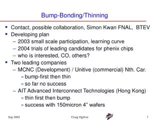
Thinning • We would like to thin the 8” wafer to 200 um from 750 um. • Checking out a few vendors (together with MCNC) • QBBS ( UV release tape) • APTEK (wax) • TRUE-Si (plasma etching, not touching the back side)
Thinning (cont) • We will chek the flatness, uniformity of the thinning here using touch probe, optically, interferometry (ANL) • 1st wafers received from MCNC (bumped 6” wafers) • Target thickness: 200 mm • Our measurement: 190 mm and 170 mm (SD about 25 mm); the thick one broke into two halves
Summary • A lot of work need to be done on thinning and protection of the bumps • QBBS – look best out of the three in terms of bump protection • Have talked to MCNC about using photoresist to protect the bumps( not easy, very thick layer) • Have sent out to these companies 8” wafers to be thinned