Disaster Management Communication System Realization: Project Presentation
This project presentation introduces a system for Disaster Management communication services. It provides a visual environment for modeling, captures customer details, and allows code generation from specified schemas. The system requirements include logging in/out, creating video schemas, and saving communication schemas. Users can load and execute schemas, create communication models, and connect shapes. The design methodology includes Meta-models for Communication and Workflow CML. Software Architecture uses Pipe & Filter and Model View Controller patterns. UML profiles and class diagrams detail the software architecture and object interactions for video creation and execution.


Disaster Management Communication System Realization: Project Presentation
E N D
Presentation Transcript
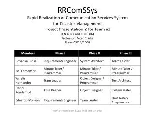
RRComSSysRapid Realization of Communication Services Systemfor Disaster Management Project Presentation 2 for Team #2 CEN 4021 and CEN 5064Professor: Peter ClarkeDate: 03/24/2009 Team 2 Presentation 2, CEN 4021 and CEN 5064
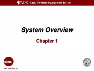
System Overview • Provides a domain-specific visual environment for the modeling of a Disaster Management communication service. • Allows the developer to capture relevant details from the customer before initiating the implementation. • Provides a generative architecture that will be transparent to developer. • Allows generating executable code from the communication schema specified. Team 2 Presentation 2, CEN 4021 and CEN 5064
System Requirements (I) • The system shall allow developers to successfully log-in into the system • The system shall allow developers to successfully log-out of the system • The system shall allow developers to create video schemas using a graphical modeling tool • The system shall allow developers to save communication schemas into the repository of models Team 2 Presentation 2, CEN 4021 and CEN 5064
System Requirements (II) • The system shall allow users to load communication schemas from the repository of models • The system shall allow users to execute communication schemas by first transforming them into communication instances and validating them • The system shall allow developers to drop shapes in the process of creation of a communication model • The system shall allow developers to connect shapes in the process of creation of a communication model Team 2 Presentation 2, CEN 4021 and CEN 5064
Design Methodology – MDSD Team 2 Presentation 2, CEN 4021 and CEN 5064
Meta-model for CML - Communication Team 2 Presentation 2, CEN 4021 and CEN 5064
Meta-model for CML - Workflow Team 2 Presentation 2, CEN 4021 and CEN 5064
Software Architecture (I) • Pipe & Filter : Used in the modeling and code generation subsystems. • Classes involved in representing the gcml and x-cml models are pipes. • Classes involved in doing the transformations to the xml files are filters. • Model View Controller : Used in the model execution subsystems. • Views are the multiple windows to enable the execution of a model • Model is the set of entities to represent the communication model. • Controller are the classes responsible for ensuring the flow of events. Team 2 Presentation 2, CEN 4021 and CEN 5064
Software Architecture (2) Team 2 Presentation 2, CEN 4021 and CEN 5064
UML Profile – Main Package Team 2 Presentation 2, CEN 4021 and CEN 5064
Class Diagram – Main Package (I) Factory Method Command Team 2 Presentation 2, CEN 4021 and CEN 5064
Class Diagram – Main Package (II) Singleton Team 2 Presentation 2, CEN 4021 and CEN 5064
Object Interaction (I) – State Machine Team 2 Presentation 2, CEN 4021 and CEN 5064
Object Interaction (2) Create 2 Way Video Team 2 Presentation 2, CEN 4021 and CEN 5064
Object Interaction (3) - Execute Two Way Video Team 2 Presentation 2, CEN 4021 and CEN 5064
The End Thank you! Questions and Answers Team 2 Presentation 2, CEN 4021 and CEN 5064