Download

1 / 41
930 likes | 2.42k Vues
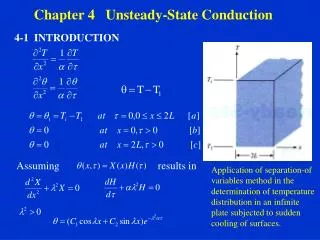
University of Palestine Engineering Hydraulics 2 nd semester 2010-2011. CHAPTER 4: Unsteady flow in pipes. Unsteady flow in pipes. Content. Water Hammer Phenomenon in pipelines. Propagation of water hammer pressure wave. Analysis of Water Hammer Phenomenon .

E N D
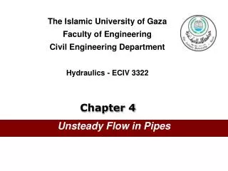
University of Palestine Engineering Hydraulics 2nd semester 2010-2011 CHAPTER 4: Unsteady flow in pipes
Unsteady flow in pipes Content Water Hammer Phenomenon in pipelines. Propagation of water hammer pressure wave. Analysis of Water Hammer Phenomenon . Time History of Pressure Wave. Stresses in the pipe wall.
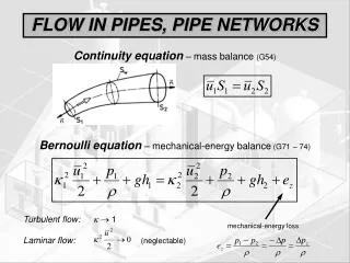
Water Hammer Phenomenon in pipelines • A sudden change of flow rate in a large pipeline (due to valve closure, pump turnoff, etc.) may involve a great mass of water moving inside the pipe. • The force resulting from changing the speed of the water mass may cause a pressure rise in the pipe with a magnitude several times greater than the normal static pressure in the pipe. • The excessive pressure may fracture the pipe walls or cause other damage to the pipeline system. • This phenomenon is commonly known as the water hammer phenomenon
Some typical damages Burst pipe in power sation Big Creek #3, USA Pump damage in Azambuja Portugal Pipe damage in power station Okigawa
Water Hammer Phenomenon in pipelines Consider a long pipe AB: • Connected at one end to a reservoir containing water at a height H from the center of the pipe. • At the other end of the pipe, a valve to regulate the flow of water is provided.
Water Hammer Phenomenon in pipelines • If the valve is suddenly closed, the flowing water will be obstructed and momentum will be destroyed and consequently a wave of high pressure will be created which travels back and forth starting at the valve, traveling to the reservoir, and returning back to the valve and so on. This wave of high pressure: • Has a very high speed(called celerity, C ) which may reach the speed of sound wave and may create noise called knocking, • Has the effect of hammering action on the walls of the pipe and hence is commonly known as the water hammer phenomenon.
Water Hammer Phenomenon in pipelines • The kinetic energy of the water moving through the pipe is converted into potential energy stored in the water and the walls of the pipe through the elastic deformation of both. • The water is compressed and the pipe material is stretched. • The following figure illustrates the formation and transition of the pressure wave due to the sudden closure of the valve
Propagation of water hammer pressure wave Steady state condition Transient condition t < L/C
Propagation of water hammer pressure wave Transient condition t = L/C Transient condition L/C >t >2L/C Transient condition t =2L/C
Propagation of water hammer pressure wave Transient condition 2L/C >t >3L/C Transient condition t = 3L/C
Propagation of water hammer pressure wave Transient condition 3L/C >t >4L/C Transient condition t = 4L/C
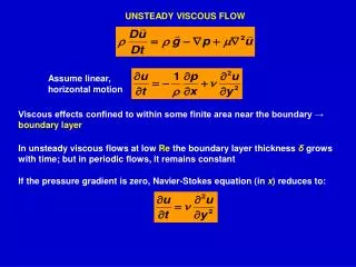
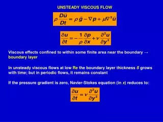
Analysis of Water Hammer Phenomenon The pressure rise due to water hammer depends upon: (a) The velocity of the flow of water in pipe, (b) The length of pipe, (c) Time taken to close the valve, (d) Elastic properties of the material of the pipe. The following cases of water hammer will be considered: • Gradual closure of valve, • Sudden closure of valve and pipe is rigid, and • Sudden closure of valve and pipe is elastic.
Analysis of Water Hammer Phenomenon • The time required for the pressure wave to travel from the valve to the reservoir and back to the valve is: Where: L = length of the pipe (m) C = speed of pressure wave, celerity (m/sec) • If the valve time of closure is tc , then • If the closure is considered gradual • If the closure is considered sudden
Analysis of Water Hammer Phenomenon The speed of pressure wave “C” depends on : • the pipe wall material. • the properties of the fluid. • the anchorage method of the pipe. • if the pipe is rigid • if the pipe is elastic and
Analysis of Water Hammer Phenomenon Where: • C = velocity (celerity) of pressure wave due to water hammer. • = water density ( 1000kg/m3 ). • Eb= bulk modulus of water ( 2.1 x 10⁹ N/m2). • Ec = effective bulk modulus of water in elastic pipe. • Ep = Modulus of elasticity of the pipe material. • e = thickness of pipe wall. • D = diameter of pipe. • K = factor depends on the anchorage method: = for pipes free to move longitudinally, = for pipes anchored at both ends against longitudinal movement = for pipes with expansion joints. • where = poisson’s ratio of the pipe material (0.25 - 0.35). It may take the value = 0.25 for common pipe materials.
Analysis of Water Hammer Phenomenon The Maximum pressure created by the water hammer
Analysis of Water Hammer Phenomenon Case 1:Gradual Closure of Valve • If the time of closure, then the closure is said to be gradual and the increased pressure is where, • V0 = initial velocity of water flowing in the pipe before pipe closure • t = time of closure. • L = length of pipe. • = water density. • The pressure head caused by the water hammer is
Analysis of Water Hammer Phenomenon Another method for closure time (t > 2 L/C)
Analysis of Water Hammer Phenomenon Case 2:Sudden Closure of Valve and Pipe is Rigid • If the time of closure , then the closure is said to be Sudden. • The pressure head due caused by the water hammer is • But for rigid pipe so:
Analysis of Water Hammer Phenomenon Case 3:Sudden Closure of Valve and Pipe is Elastic • If the time of closure, then the closure is said to be Sudden. • The pressure head caused by the water hammer is • But for elastic pipe so:
Analysis of Water Hammer Phenomenon Water hammer pressure head • Applying the water hammer formulas we can determine the energy gradient line and the hydraulic gradient line for the pipe system under steady flow condition. Due to water hammer HA Water Hammer Pressure in a Pipeline So the total pressure at any point M after closure (water hammer) is or
Time History of Pressure Wave • The time history of the pressure wave for a specific point on the pipe is a graph that simply shows the relation between the pressure increase ( ) and time during the propagation of the water hammer pressure waves.
Time History of Pressure Wave • For example, considering point “A” just to the left of the valve. • Note: friction (viscosity) is neglected. 1 Time history for pressure at point “A” (after valve closure)
Time History of Pressure Wave The time history for point “M” (at midpoint of the pipe) 1 Note: friction (viscosity) is neglected.
Time History of Pressure Wave The time history for point B (at a distance x from the reservoir ) t*(2L/C) 1 Note: friction (viscosity) is neglected. This is a general graph where we can substitute any value for x (within the pipe length) to obtain the time history for that point.
Time History of Pressure Wave In real practice friction effects are considered and hence a damping effect occurs and the pressure wave dies out, i.e.; energy is dissipated. Damping effect of friction t*(2L/C) the time history for pressure at point “A” when friction (viscosity) is included
Stresses in the pipe wall • After calculating the pressure increase due to the water hammer, we can find the stresses in the pipe wall: • Circumferential (hoop) stress “fc :” • Longitudinal stress “fL”: where: D = pipe inside diameter tp = pipe wall thickness = total pressure = initial pressure (before valve closure) + pressure increase due water hammer.
Note In water hammer analysis the time history of pressure oscillation in the pipe line is determined. Because of the friction effect the oscillation gradually dies out To keep the water hammer pressure within manageable limits, valves are commonly design with closure times considerably greater than 2L/C
Example 2 • A cast iron pipe with 20 cm diameter and 15 mm wall thickness is carrying water from a reservoir. At the end of the pipe a valve is installed to regulate the flow. The following data are available: • e = 0.15 mm (absolute roughness) , • L = 1500 m (length of pipe), • Q = 40 l/sec (design flow) , • K = 2.1 x 10⁹ N/m2 (bulk modulus of water), • E = 2.1 x 10¹¹ N/m2 (modulus of elasticity of cast iron), • = 0.25 (poisson’s ratio), • = 1000 kg/m3 • T = 150 C.
Example 2.cont. Find , , fc , and fL due to the water hammer produced for the following cases: • Assuming rigid pipe when tc = 10 seconds, and tc = 1.5 seconds. • Assuming elastic pipe when tc = 10 seconds, and tc = 1.5 seconds, if: • the pipe is free to move longitudinally, • the pipe is anchored at both ends and throughout its length, • the pipe has expansion joints. • Draw the time history of the pressure wave for the case (b-3) at: • a point just to the left of the valve, and • a distance x = 0.35 L from the reservoir. • Find the total pressure for all the cases in (b-3).
http://www.haestad.com/library/books/awdm/online/wwhelp/wwhimpl/java/html/wwhelp.htmhttp://www.haestad.com/library/books/awdm/online/wwhelp/wwhimpl/java/html/wwhelp.htm