Combinatorial Circuit Design
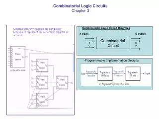
Combinatorial Circuit Design. CT213 – Computing Systems Organization. Combinatorial Circuit Design. Some useful components can be designed using the gates and the components described so far during the course


Combinatorial Circuit Design
E N D
Presentation Transcript
Combinatorial Circuit Design CT213 – Computing Systems Organization
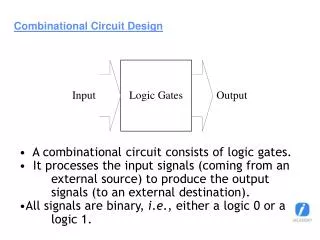
Combinatorial Circuit Design • Some useful components can be designed using the gates and the components described so far during the course • This presentation describes the design of a binary coded decimal (BCD) to 7 segment decoder, which is used in digital displays • This design will use only combinatorial logic gates, making use of the minimization logic techniques we have described
Design Requirements Design the logic circuitry that will drive a seven segment LED display and will be able to represent numbers from 0 to 9
Possible numbers and their representation on 7 segment display
Signal a implementation a = f(X3, X2, X1, X0) = X3 + X1 + X2X0 + X2’X1’X0’
Signal b implementation b = f(X3, X2, X1, X0) = X1’X0’ + X1X0 + X2’
Signal c implementation c = f(X3, X2, X1, X0) = X1’+ + X0 + X2
Signal d implementation d = f(X3, X2, X1, X0) = X3X1’X0’+ + X2’X1’X0’ + X3’X2’X1 + X2X1’X0 + X1X0’
Signal e implementation e = f(X3, X2, X1, X0) = X1X0’ + X2’X1’X0’
Signal f implementation f = f(X3, X2, X1, X0) = X3 + X2X0’ + X1’X0’ + X2X1’
Signal g implementation g = f(X3, X2, X1, X0) = X3 + X1’X0’ + X2X1’ + X2’X1
7 segment display • All the anode segments are connected together • Power must be applied externally to the anode connection that is common to all the segments • By applying the ground to a particular segment (i.e. a,b,g etc..), the appropriate segment will light up
7 segment common anode • A resistor should be added in order to limit the current through LED • The current to light the active LED is sink by the logic component, which is preferable
7 segment display • All the cathode of the LED are connected together • The common connection must be grounded and power must be applied to appropriate segment in order to illuminate that segment • The current to light the active LED is generated by the logic component, which generates the logic 1
7447 TTL IC • Real world example of BCD to 7 segment decoder • Outputs of the decoder are active low and a common anode 7 segment display is used
References • “Computer Systems Organization & Architecture”, John D. Carpinelli, ISBN: 0-201-61253-4