Sequential Circuit Design
Sequential Circuit Design. Sequential Logic Design. Contents Why sequential logic? Flip-flop criteria table Sequential circuit analysis Sequential circuit design. Why Sequential Logic?. Sequential circuit has additional dimension which is time


Sequential Circuit Design
E N D
Presentation Transcript
Sequential Circuit Design MOHD. YAMANI IDRIS/ NOORZAILY MOHAMED NOOR
Sequential Logic Design Contents • Why sequential logic? • Flip-flop criteria table • Sequential circuit analysis • Sequential circuit design MOHD. YAMANI IDRIS/ NOORZAILY MOHAMED NOOR
Why Sequential Logic? • Sequential circuit has additional dimension which is time • Combinational logic only depends on current input • Sequential circuit output depends on previous input other than current input • More powerful than combination logic • Able to model condition which can’t be modeled by combinational logic MOHD. YAMANI IDRIS/ NOORZAILY MOHAMED NOOR
Sequential Circuit Analysis • Given sequential circuit diagram, behavioral analysis from state table and also state diagram • Need state equations to get flip-flop input and output functions for circuit output other than flip-flop (if any) • We use A(t) and A(t+1) to represent current condition and the next condition for flip-flop represented by A. • Other method, we can use A and A+ to represent current condition and the following condition MOHD. YAMANI IDRIS/ NOORZAILY MOHAMED NOOR
Sequential Circuit Analysis • Example 1 (using D flip-flop) State equation Output Function MOHD. YAMANI IDRIS/ NOORZAILY MOHAMED NOOR
Sequential Circuit Analysis • From the state equations and output function, we can derive state table which contains all combined binary available for current condition and input • State table • The same as Truth Table • Input and condition pad on the left • Output and next condition on the right • combined binary available for current condition and input • M flip-flop and n input => 2m+n line MOHD. YAMANI IDRIS/ NOORZAILY MOHAMED NOOR
Sequential Circuit Analysis State equation Output function State table for circuit in Example 1 MOHD. YAMANI IDRIS/ NOORZAILY MOHAMED NOOR
Sequential Circuit Analysis Other method MOHD. YAMANI IDRIS/ NOORZAILY MOHAMED NOOR
Sequential Circuit Analysis • From the truth table, we can draw state diagram • State diagram • Each state is represented by circle • Each arrow (between two circle) represent transfer for sequential logic (i.e. line transition in truth table) • a/b label for each arrow where a represent inputs and b represent output for circuit in transition • Each flip-flop value combination represent state. Therefore, m flip-flop=> until 2m state. MOHD. YAMANI IDRIS/ NOORZAILY MOHAMED NOOR
Sequential Circuit Analysis State diagram for circuit in example 1 MOHD. YAMANI IDRIS/ NOORZAILY MOHAMED NOOR
Flip-flop Input Function • Output of sequential circuit is function for current condition for flip-flop and input. This is explained using algebra by circuit output function • In example 1: y= (A+B)x’ • Circuit part that generate input to flip-flop is explained using algebra by flip-flop input functions MOHD. YAMANI IDRIS/ NOORZAILY MOHAMED NOOR
Flip-flop Input Function • Flip-flop input function determine next condition • From flip-flop input function and criteria table for flip-flop, we get next condition of the flip-flop MOHD. YAMANI IDRIS/ NOORZAILY MOHAMED NOOR
Flip-flop Input Function • Example 2: circuit with JK flip flop • We use 2 character to represent flip-flop input: first character represent flip-flop input (J or K for JK flip-flop, S or R for SR flip-flop, D for D flip-flop, T for T flip-flop ) and second character represent name of the flip-flop MOHD. YAMANI IDRIS/ NOORZAILY MOHAMED NOOR
Analysis: Example 3 • Given sequential circuit with two JK flip-flop, A and B and one input x • Get the input flip-flop function from the circuit MOHD. YAMANI IDRIS/ NOORZAILY MOHAMED NOOR
Analysis: Example 3 • Input flip-flop function • Fill the state table with the above function using criteria table for used flip-flop MOHD. YAMANI IDRIS/ NOORZAILY MOHAMED NOOR
Analysis: Example 3 • Draw state diagram from the state table MOHD. YAMANI IDRIS/ NOORZAILY MOHAMED NOOR
Flip-flop Excitation Tables • Analysis: Start from circuit diagram, build state table or state diagram • Design: Start from specification set (i.e. in state equation form, state table or state diagram) build logic circuit. • Criteria table is used in analysis • Excitation tables is used in design MOHD. YAMANI IDRIS/ NOORZAILY MOHAMED NOOR
Flip-flop Excitation Tables • Excitation tables : it give transition characteristic between current condition and next condition to determine flip-flop input MOHD. YAMANI IDRIS/ NOORZAILY MOHAMED NOOR
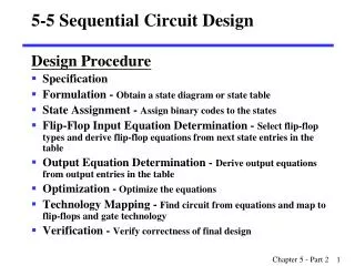
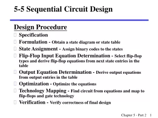
Designing Sequential Circuit Design steps • Start with circuit spesification – characteristic of circuit • Build state table • Do state reduction if needed (not in syllabus) • Do state assignment (not in syllabus) • Determine number of flip-flop which will be used • Build circuit excitation and output table from state table • Build circuit output function and flip-flop input function • Draw logic diagram MOHD. YAMANI IDRIS/ NOORZAILY MOHAMED NOOR
Design: Example 1 • Given state diagram as follows, get the sequential circuit using JK flip-flop MOHD. YAMANI IDRIS/ NOORZAILY MOHAMED NOOR
Design: Example 1 • State/excitation table using JK flip-flop MOHD. YAMANI IDRIS/ NOORZAILY MOHAMED NOOR
Design: Example 1 • Block diagram MOHD. YAMANI IDRIS/ NOORZAILY MOHAMED NOOR
Design: Example 1 • From state table, get input flip-flop function MOHD. YAMANI IDRIS/ NOORZAILY MOHAMED NOOR
Design: Example 1 • Input flip-flop function • Logic Diagram MOHD. YAMANI IDRIS/ NOORZAILY MOHAMED NOOR
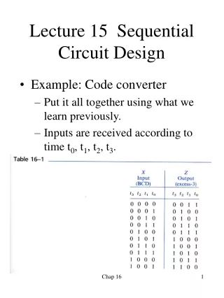
Design: Example 2 • Design, using D flip-flop, circuit is based on state table below. (Exercise: How if using JK flip-flop) MOHD. YAMANI IDRIS/ NOORZAILY MOHAMED NOOR
Design: Example 2 • Determine input expression for flip-flop and y output MOHD. YAMANI IDRIS/ NOORZAILY MOHAMED NOOR
Design: Example 2 • From expression built, draw logic diagram MOHD. YAMANI IDRIS/ NOORZAILY MOHAMED NOOR
Design a Synchronous Counter • Counter: sequential circuit cycle through state sequence • Binary counter: follow binary sequence. n-bit binary counter (with n flip-flop) able to count from 0 to 2n-1. • Example 1: 3-bit binary counter (using T flip-flop) MOHD. YAMANI IDRIS/ NOORZAILY MOHAMED NOOR
Design a Synchronous Counter • 3-bit binary counter (cont) MOHD. YAMANI IDRIS/ NOORZAILY MOHAMED NOOR
Design a Synchronous Counter • 3-bit binary counter (cont) MOHD. YAMANI IDRIS/ NOORZAILY MOHAMED NOOR