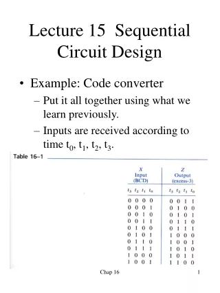
CMOS SEQUENTIAL CIRCUIT DESIGN
CMOS SEQUENTIAL CIRCUIT DESIGN. Integrated Circuits Spring 2001 Dept. of ECE University of Seoul. Combinational vs. Sequential Logic. Combinational Logic OUT(t) IN(t). Sequential Logic OUT(t) IN(t) IN(t-kT) OUT(t-kT). Positive Feedback Charge on Cap.


CMOS SEQUENTIAL CIRCUIT DESIGN
E N D
Presentation Transcript
CMOS SEQUENTIAL CIRCUIT DESIGN Integrated Circuits Spring 2001 Dept. of ECE University of Seoul
Combinational vs. Sequential Logic • Combinational Logic • OUT(t) IN(t) Sequential Logic OUT(t) IN(t) IN(t-kT) OUT(t-kT) Positive Feedback Charge on Cap.
Sequential Logic w/ Positive Feedback • Two Inverters in Positive Feedback • STATIC
Bi-stability • Transition Region Stable Regions • Slope (Gain) >1
R S Q Q S Q 0 Q 0 Q S Q 0 0 1 1 Q R 0 1 0 1 Q R 1 0 1 0 R S Q Q S Q S Q 1 Q 1 Q Q R 0 1 1 0 Q R 1 0 0 1 0 1 0 1 SR Latch • NOR-Based NAND-Based
L H H Q L L H ? Q H H H L H HL L L H JK Flip-Flop f=H
H L L L H H L H Master/Slave Flip-Flop • master slave One-Catching Level-Sensitive Input Data Valid @ f=High
Flip-Flop Timing Constraints • Setup Time tsetup Hold Time thold • Propagation Delay tpFF
Flip-Flop Timing Example • T > tpFF + tp,comb + tsetup f Y Q FF’s LOGIC tp,comb
Pseudo-Static D-Latch f=High (Data I/O) f=Low (Data Store)
M/S D-FF (pseudo-Static) • f=High New Data In & Previous Data Store f=Low New Data Out & New Data Store
M/S D-FF Problem Solution Non-Overlapping 2-Phase Clocks