5-5 Sequential Circuit Design
5-5 Sequential Circuit Design. Design Procedure Specification Formulation - Obtain a state diagram or state table State Assignment - Assign binary codes to the states

5-5 Sequential Circuit Design
E N D
Presentation Transcript
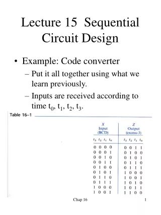
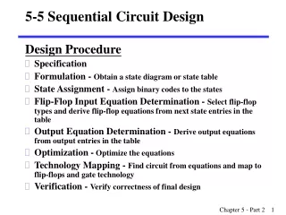
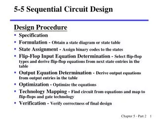
5-5 Sequential Circuit Design Design Procedure • Specification • Formulation - Obtain a state diagram or state table • State Assignment - Assign binary codes to the states • Flip-Flop Input Equation Determination - Select flip-flop types and derive flip-flop equations from next state entries in the table • Output Equation Determination - Derive output equations from output entries in the table • Optimization - Optimize the equations • Technology Mapping - Find circuit from equations and map to flip-flops and gate technology • Verification - Verify correctness of final design
Finding a State Diagram • In specifying a circuit, we use states to remember meaningful properties of past input sequences that are essential to predicting future output values. • A sequence recognizer is a sequential circuit that produces a distinct output value whenever a prescribed pattern of input symbols occur in sequence, i.e, recognizes an input sequence occurence. • We will develop a procedure specific to sequence recognizers to convert a problem statement into a state diagram. • Next, the state diagram, will be converted to a state table from which the circuit will be designed.
Initial state • When the power in a digital system is first turned on, the state of the flip-flop is unknown. • In this chapter, the circuits we design must have known initial state • Reset or master reset is needed. • Asynchronous reset • Synchronous reset Fig 5-19
Example 5-3 Sequence Recognizer • Example: Recognize the sequence 1101 • Note that the sequence 1111101 contains 1101 and "11" is a proper sub-sequence of the sequence. • Thus, the sequential machine must remember that the first two one's have occurred as it receives another symbol. • Also, the sequence 1101101 contains 1101 as both an initial subsequence and a final subsequence with some overlap, i. e., 1101101 or 1101101. • And, the 1 in the middle, 1101101, is in both subsequences. • The sequence 1101 must be recognized each time it occurs in the input sequence.
Example: Recognize 1101 1/0 A B • Define states for the sequence to be recognized: • assuming it starts with first symbol, • continues through each symbol in the sequence to be recognized, and • uses output 1 to mean the full sequence has occurred, • with output 0 otherwise. • Starting in the initial state (Arbitrarily named "A"): • Add a state that recognizes the first "1." • State "A" is the initial state, and state "B" is the state which represents the fact that the "first" one in the input subsequence has occurred. The output symbol "0" means that the full recognized sequence has not yet occurred.
Example: Recognize 1101 (continued) 1/0 1/0 A B C 1/1 1/0 0/0 1/0 D A B C • After one more 1, we have: • C is the state obtained when the input sequence has two "1"s. • Finally, after 110 and a 1, we have: • Transition arcs are used to denote the output function (Mealy Model) • Output1on the arc from D means the sequence has been recognized • To what state should the arc from state Dgo? Remember: 1101101 ? • Note that D is the last state but the output 1 occurs for the input applied in D. This is the case when a Mealy model is assumed.
Example: Recognize 1101 (continued) 1/1 1/0 0/0 1/0 A B C D 1/0 0/0 1/0 A B C D 1/1 • Clearly the final 1 in the recognized sequence 1101 is a sub-sequence of 1101. It follows a 0 which is not a sub-sequence of 1101. Thus it should represent the same state reached from the initial state after a first 1 is observed. We obtain:
Example: Recognize 1101 (continued) 1/0 0/0 1/0 A B C D 1/1 • The state have the following abstract meanings: • A: No proper sub-sequence of the sequence has occurred. • B: The sub-sequence 1 has occurred. • C: The sub-sequence 11 has occurred. • D: The sub-sequence 110 has occurred. • The 1/1 on the arc from D to B means that the last 1 has occurred and thus, the sequence is recognized.
Example: Recognize 1101 (continued) • The other arcs are added to each state for inputs not yet listed. Which arcs are missing? • Answer: "0" arc from A "0" arc from B "1" arc from C "0" arc from D. 1/0 0/0 1/0 A B C D 1/1
Example: Recognize 1101 (continued) 0/0 1/0 1/0 0/0 1/0 A B D 0/0 1/1 0/0 • State transition arcs must represent the fact that an input subsequence has occurred. Thus we get: • Note that the 1 arc from state C to state C implies that State C means two or more 1's have occurred. C
Formulation: Find State Table 0/0 0/0 1/0 1/0 0/0 1/0 1/0 A B C D 0/0 1/1 0/0 Present Next State Output State x=0 x=1 x=0 x=1 0 0 A B A B C D • From the State Diagram, we can fill in the State Table. • There are 4 states, one input, and one output. We will choose the form with four rows, one for each current state. • From State A, the 0 and 1 input transitions have been filled in along with the outputs.
Formulation: Find State Table 0/0 1/0 1/0 0/0 1/0 A B C D 0/0 1/1 0/0 • From the state diagram, we complete the state table. • What would the state diagram and state table look like for the Moore model? Present Next State Output State x=0 x=1 x=0 x=1 A A B 0 0 B A C 0 0 C D C 0 0 D A B 0 1
Example: Moore Model for Sequence 1101 • For the Moore Model, outputs are associated with states. • We need to add a state "E" with output value 1 for the final 1 in the recognized input sequence. • This new state E, though similar to B, would generate an output of 1 and thus be different from B. • The Moore model for a sequence recognizer usually has more states than the Mealy model.
Example: Moore Model (continued) 0 1 0 1 1 A/0 B/0 C/0 D/0 0 1 1 0 E/1 0 • We mark outputs on states for Moore model • Arcs now show only state transitions • Add a new state E to produce the output 1 • Note that the new state, E produces the same behavior in the future as state B. But it gives a different output at the present time. Thus these states do represent a different abstraction of the input history.
Example: Moore Model (continued) 0 1 0 1 1 A/0 B/0 C/0 D/0 0 1 1 0 E/1 0 Present Next State Output State x=0 x=1 y A A B 0 B A C 0 C D C 0 D A E 0 E A C 1 • The state table is shown below • Memory aid: more state in the Moore model: “Moore is More.”
State Assignment • Counting Order Assignment: A = 0 0, B = 0 1, C = 1 0, D = 1 1 • The resulting coded state table:
State Assignment (continued) • Gray Code Assignment: A = 0 0, B = 0 1, C = 1 1, D = 1 0 • The resulting coded state table:
Find Flip-Flop Input and Output Equations– Gray Code Assignment • Assume D flip-flops (two is needed for 4 states) • Obtain K-maps for DA, DB, and Z:
Implementation A D C R Z B D X Clock C R Reset • Circuit: • Gate input cost: combinational logic: 9 flip-flop: 28 (=14×2) total: 37
State Assignment (continued) • One-Hot Assignment : A =1000, B = 0100, C = 0010, D = 0001 The resulting coded state table:
Other Flip-Flop Types • J-K and T flip-flops • Behavior • Implementation • Basic descriptors for understanding and using different flip-flop types • Characteristic tables • Characteristic equations • Excitation tables • For actual use, see Reading Supplement - Design and Analysis Using J-K and T Flip-Flops
J-K Flip-flop • Behavior • Same as S-R flip-flop with J analogous to S and K analogous to R • Except that J = K = 1 is allowed, and • For J = K = 1, the flip-flop changes to the opposite state • As a master-slave, has same “1s catching” behavior as S-R flip-flop • If the master changes to the wrong state, that state will be passed to the slave • E.g., if master falsely set by J = 1, K = 1 cannot reset it during the current clock cycle
J-K Flip-flop (continued) J C K D J K C • Symbol • Implementation • To avoid 1s catchingbehavior, one solutionused is to use anedge-triggered D asthe core of the flip-flop Why?
T Flip-flop • Behavior • Has a single input T • For T = 0, no change to state • For T = 1, changes to opposite state • Same as a J-K flip-flop with J = K = T • As a master-slave, has same “1s catching” behavior as J-K flip-flop • Cannot be initialized to a known state using the T input • Reset (asynchronous or synchronous) essential
T Flip-flop (continued) T C D T C • Symbol • Implementation • To avoid 1s catchingbehavior, one solutionused is to use anedge-triggered D asthe core of the flip-flop
Basic Flip-Flop Descriptors • Used in analysis • Characteristic table - defines the next state of the flip-flop in terms of flip-flop inputs and current state • Characteristic equation - defines the next state of the flip-flop as a Boolean function of the flip-flop inputs and the current state • Used in design • Excitation table - defines the flip-flop input variable values as function of the current state and next state
D Flip-Flop Descriptors D Q(t 1) Operation + 0 0 Reset 1 1 Set Operation Q(t +1) D 0 0 Reset 1 1 Set • Characteristic Table • Characteristic Equation Q(t+1) = D • Excitation Table
T Flip-Flop Descriptors • Characteristic Table • Characteristic Equation Q(t+1) = T Å Q • Excitation Table + T Q(t 1) Operation 0 Q ( t ) No change 1 Q ( t ) Complement + Q(t 1) T Operation Q ( t ) 0 No change Q ( t ) 1 Complement
S-R Flip-Flop Descriptors Q(t) Q(t+ 1) S R Operation 0 0 0 X No change 0 1 1 0 Set 1 0 0 1 Reset 1 1 X 0 No change • Characteristic Table • Characteristic Equation Q(t+1) = S + R Q, S.R = 0 • Excitation Table S R Q(t + 1) Operation 0 0 Q ( t ) No change 0 1 0 Reset 1 0 1 Set 1 1 ? Undefined
J-K Flip-Flop Descriptors J K Q(t + 1) Operation 0 0 Q ( t ) No change 0 1 0 Reset 1 0 1 Set 1 1 Complement Q ( t ) • Characteristic Table • Characteristic Equation Q(t+1) = J Q + K Q • Excitation Table + 1) Q(t) Q(t J K Operation 0 0 0 X No change 0 1 1 X Set 1 0 X 1 Reset 1 1 X 0 No Change
Flip-flop Behavior Example D T C C • Use the characteristic tables to find the output waveforms for the flip-flops shown: Clock D,T QD QT
Flip-Flop Behavior Example (continued) S C R J C K • Use the characteristic tables to find the output waveforms for the flip-flops shown: Clock S,J R,K QSR ? QJK