Understanding the Analog Feedback Machine: A Comprehensive Guide to Circuits and Components
Dive into the world of electronics with an in-depth look at the Analog Feedback Machine. This guide presents a full schematic and parts list, comparing electricity to water flow to enhance understanding. Learn the basics of DC circuits, including components such as batteries, resistors, capacitors, and transistors. We will explore how current flows, the role of operational amplifiers, and how to amplify and combine signals effectively. Perfect for beginners and enthusiasts eager to grasp the fundamentals of electronic circuits!

Understanding the Analog Feedback Machine: A Comprehensive Guide to Circuits and Components
E N D
Presentation Transcript
Water Analogy - How Electricity Moves Voltage = Water Pressure - Stored Potential Energy Current = The Amount of water flowing through an area at a given time. Positive current convention tracks flow from positive voltage to negative Electrons flow from negative to positive.
Electricity Basics - The DC Circuit Battery Lamp Switch
Electricity Basics - The DC Circuit Current flows when the switch is closed.
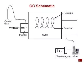
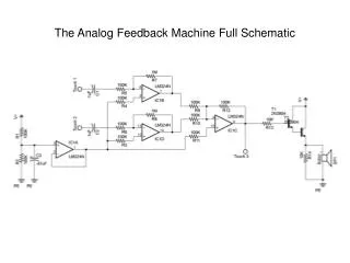
Basic Theory + Parts • Imagine a circuit like a system of pipes and valves • Battery = water pump • Conductors/Wires = main pipes • Resistors = smaller pipes of varying sizes • Capacitors = water balloons • Transistors = valves controlled by water flow • Integrated Circuits = pre-built, super miniature circuits
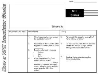
Transistors Transistors come in many flavors these days. Bipolar Transistors are semiconductor components with the three connections: Base, Emitter, and Collector A small current flow applied to the Base of the transistor permits a larger (and proportional) current flow between the Collector and Emitter NPN - is active when a positive current relative to the emitter is applied to its base PNP - is active when a negative current relative to its emitter is applied to its base NPN PNP
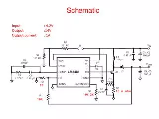
Transistors can be used as an electrically controlled switch! Applying a positive current to the base of T1 at 5 volts through the 47k ohm resistor causes it to go into saturation.
Transistors can be used to drive LEDS as shown: Applying a positive current to the base of T1 at 5 volts through the 47k ohm resistor causes it to go into saturation. Current then flows through R1 and the LED causing it to light.
IMPORTANT NOTE! • Our Transistors have a non-standard pin-out • From Left to Right (with flat side facing you and legs pointed down) Pin 1 = EMITTER Pin 2 = COLLECTOR Pin 3 = BASE
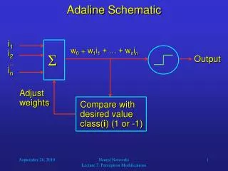
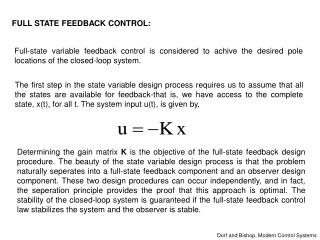
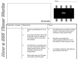
Operational Amplifiers • Two inputs • Non-Inverting (+) • Inverting (-) • Fixed gain factor • Open loop gain • Feedback used to control gain and to produce other useful circuits.
Virtual Ground • Analog audio signals swing both positive and negative relative to a fixed voltage. • When powering audio electronics from a battery supply, a virtual ground reference must be generated. • This can be done using a voltage divider and a voltage follower.
Circuit Breakdown • Inputs • Touch Pads (thumb tacks optional) • Circuits • Voltage Divider • Voltage Follower • Inverting Amplifier • Summing Amplifier