Download
1 / 20
210 likes | 371 Vues
Biomedical Imaging 2. Class 1 – Introduction 01/22/08. Course instructor. Dr. Harry L. Graber Research Assistant Professor of Pathology / SUNY Downstate Medical Center / Room BSB 4-132, (718) 270-1286 / harry.graber@downstate.edu

E N D
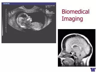
Biomedical Imaging 2 Class 1 – Introduction 01/22/08
Course instructor Dr. Harry L. GraberResearch Assistant Professor of Pathology / SUNY Downstate Medical Center / Room BSB 4-132, (718) 270-1286 / harry.graber@downstate.edu A.B., Chemistry 1983, Washington University, St. Louis, MO Ph.D., Physiology and Biophysics 1998, SUNY Health Science Center, Brooklyn, NY Postdoctoral Fellow 1998, SUNY Downstate Medical Center Res. Asst. Professor 2001, SUNY Downstate Medical Center Research Focus: Optical Tomography - Image Reconstruction and Signal Analysis
Lecture hours / locations, credits • Classes • Location: SUNY DMC HSEB 8J • Hours: Tuesday, 10:00 AM to 1:00 PM • Credits • Classroom Participation: 15% • Homework: 20% • Exam1: 30% • Exam2: 35%
Course materials • No specific textbook • Topic-specific readings (research papers, review papers, scientific magazine articles, internet pages) will be provided as needed • Lecture notes and copies of assigned readings will be posted for download at http://OTG.downstate.edu/download.htm
Imaging Modalities Covered in BMI1 • X-ray Projection Radiography • X-ray Computed Tomography • Nuclear Imaging • Planar Scintigraphy • Positron Emission Tomography • Single Photon Emission Computed Tomography • Ultrasound • Magnetic Resonance Imaging • Structural MRI (anatomy)
Imaging Modalities Covered in BMI1 • In brief, structural imaging (SI) techniques • With one significant exception
Imaging Modalities Covered in BMI2 • Functional imaging (FI) methods • Diffuse Optical Tomography • Optical Coherence Tomography • Functional MRI (fMRI) • Electroencephalographic Imaging • Magnetoencephalography • Combined, or multi-mode, imaging • But what does “functional” mean?
Meaning of “functional” is context-specific • Always involves examination of what tissue is doing • But how this examination is carried out is different for different methods • In some cases, functional imaging just means producing as many structural images as you can, as fast as you can • Example: functional x-ray CT • Same goes for some kinds of functional ultrasound • What about MRI?
Varieties of fMRI • Diffusion-weighted Imaging • Perfusion Imaging • Contrast-agent-based • Magnetic Resonance Angiography / Venography • Saturation-based • Bipolar-gradient-based • Arterial Spin Labeling • Diffusion Tensor Imaging • Magnetic Susceptibility Imaging • Contrast-agent-based • Blood Oxygen Level Dependent
Some Modalities Are Inherently Functional • A: Abdominal x-ray CT image (structural/anatomical) • B: PET image of same tissue section (functional) • C: Co-registered x-ray CT and PET images
FI Usually Is More “Indirect” than SI • Direct imaging = (essentially) no math needed • Laws of physics do the work • e.g., Project an image onto a piece of film with a lens • Indirect imaging = lots of math required • Computers used to process the measurement data and reconstruct images • “More indirect” means that additional, post-reconstruction operations are needed • Usually involves some type of comparison among images from data collected at different times
Instructional Emphasis • Image contrast mechanisms • How is energy interacting with matter (i.e., tissue) • What is the image a picture of? • Biological/clinical motivation • Why do we care about the parameter(s) in the image? • How is having this image going to help us? • How will it affect the treatment our patient is getting? • Data analysis “from soup to nuts” • Pre-processing operations • Image reconstruction • Post-processing operations • “Post-post-” processing operations
Tentative Syllabus • 01/22 Introduction; diffuse optical tomography (DOT) • 01/29 DOT • 02/05 Image post-processing & time-series analysis, Pt. 1 • 02/12 Optical coherence tomography (OCT) • 02/19 fMRI – diffusion-weighted, perfusion • 02/26 fMRI – perfusion • 03/04 Exam1 • 03/11 fMRI – BOLD • 03/18 OSA Conference, no class • 03/25 Image post-processing & time-series analysis, Pt. 2 • 04/01 fMRI – diffusion-tensor imaging • 04/08 EEG/MEG principles • 04/15 EEG imaging • 04/22 MEG imaging • 04/29 DOT’s “relatives”: fluorescence OT, bioluminescence OT, correlation tomography, optoacoustic tomography • 05/06 Exam2 • 05/13 Wrap-up
Diffuse Optical tomography (DOT) • Year discovered: ~1988 • Form of radiation: Near-infrared light (non- ionizing) • Energy / wavelength of radiation: ~1 eV / 600–1000 nm • Imaging principle: Interaction (absorption, elastic scattering) of light w/ tissue • Imaging volume: ~103 cm3 • Resolution: Low (~1cm) • Applications: Perfusion, functional imaging
Source Object Detector DOT and CT: Superficial Similarities, Essential Differences • Generation: x-ray tube • Detection: Detector arrays (ion.-chambers, scint. + photodiode) • Computer reconstruction of 2D slices/ 3D volumetric images
detector light source D S screen / detector light source light source screen / detector obstacle (absorber) obstacle (absorber) S Clear medium Scattering medium D D D D Principles of DOT • Scattering dominated • Limited penetration depth (~cm), low res. (mm-cm) • Economic, functional (hemodynamics)
Source / Detector 1 Detector 2 2-3 cm Detector 3 Scalp Bone CSF Cortex DOT Instrumentation
DOT Applications Brain SPECT Breast Arm