Download

1 / 20
200 likes | 604 Vues
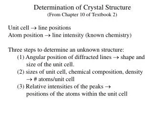
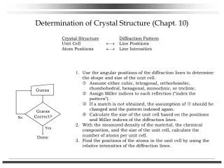
Determination of Crystal Structure (Chapt. 10). 1. Use the angular positions of the diffraction lines to determine the shape and size of the unit cell. Assume either cubic, tetragonal, orthorhombic, rhombohedral, hexagonal, monoclinic, or triclinic.

E N D
Determination of Crystal Structure (Chapt. 10) 1. Use the angular positions of the diffraction lines to determine the shape and size of the unit cell. Assume either cubic, tetragonal, orthorhombic, rhombohedral, hexagonal, monoclinic, or triclinic. Assign Miller indices to each reflection (“index the pattern”). If a match is not obtained, the assumption of should be changed and the pattern indexed again. Calculate the size of the unit cell based on the positions and Miller indices of the diffraction lines. 2. With the measured density of the material, the chemical composition, and the size of the unit cell, calculate the number of atoms per unit cell. 3. Find the positions of the atoms in the unit cell by using the relative intensities of the diffraction lines. Guess Guess Correct? No Yes Done
Preliminary Treatment of Data We want the values of sin2q for each diffraction line (in order to find the cell size and shape), however, there can be errors to what we measure, including extraneous lines in the diffraction pattern, and systematic errors (misalignment, film shrinkage, absorption, etc.) Extraneous Lines 1. X-ray beam with multiple wavelengths: 2. Contaminants or impurities in the sample, or the specimen mount! Systematic Errors 1. Film shrinkage (see Fig. 6-5 Cullity) 2. Specimen is off-centered in Debye-Scherrer camera (see Fig. 11-3 Cullity) 3. Absorption in the sample Answer mix in a reference material and calibrate. (see Fig. 10-1 Cullity)
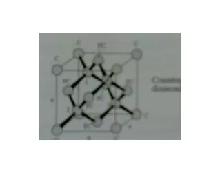
Cubic Crystals (Indexing the Patterns) Simple cubic: 1, 2, 3, 4, 5, 6, 8, 9, 10, 11, 12, 13, 14, etc. Body-centered cubic: 2, 4, 6, 8, 10, 12, 14, 16, . . . Face-centered cubic: 3, 4, 8, 11, 12, 16, 19, 20, . . . Diamond cubic: 3, 8, 11, 16, 19, 24, 27, 32, . . .
Corrections for Systematic Errors Absorption error can be lumped into this error.
Correction for Systematic Error Differentiation of Bragg’s Law: For a cubic crystal: Fractional error in a (goes to zero as q 90)
Correction for Systematic Error At small f (large q), this could be approximated as:
Indexing Patterns for Non-Cubic Crystals Tetragonal Depends on (c/a), but not on a.
Indexing Patterns for Non-Cubic Crystals Tetragonal Depends on (c/a), but not on a.
Scales for Left Side of Above Equations d scale sin2q scale
Zinc Example (Cu Ka) From table 10-2 (sin2q)
10-5 10-7 10-8