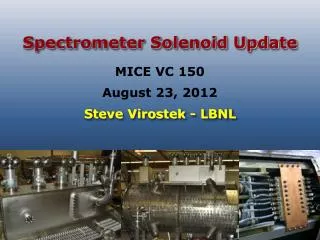
MOLLER Spectrometer Update
MOLLER Spectrometer Update. Juliette M. Mammei. Outline. The Physics Search for physics beyond the Standard Model Interference of Z boson with single photon in Møller scattering Measure the weak charge of the electron and sin 2 θ W

MOLLER Spectrometer Update
E N D
Presentation Transcript
MOLLER Spectrometer Update Juliette M. Mammei
Outline • The Physics • Search for physics beyond the Standard Model • Interference of Z boson with single photon in Møller scattering • Measure the weak charge of the electron and sin2θW • Sensitivity comparable to the two high energy collider measurements • The Experiment • High rate, small backgrounds – 150 GHz, 8% backgrounds • Novel toroid design, with multiple current returns • Full azimuthal acceptance, scattering angles from 5.5-19 mrads, 2.5-8.5 GeV • 150cm (5 kW) target, detectors 28m downstream Magnet Advisory Group Meeting October 14, 2013
The Physics e- e- APV= 35.6 ± 0.73 ppb e- e- Magnet Advisory Group Meeting October 14, 2013
Measurement of sin2θW MOLLER Z-pole MOLLER Erler, Kurylov, Ramsey-Musolf Erler Magnet Advisory Group Meeting October 14, 2013
The Experiment Detector Array Roman Pots (for tracking detectors) Hybrid Torus Upstream Torus Scattering Chamber Target Collimators 28 m Incoming Beam Magnet Advisory Group Meeting October 14, 2013
100% Azimuthal Acceptance e- e- Forward Backward e- e- COM Frame Any odd number of coils will work e- e- e- e- Lab Frame Backward Forward Magnet Advisory Group Meeting October 14, 2013
Tracks in GEANT4 Mollers eps Magnet Advisory Group Meeting October 14, 2013 (Rate weighted 1x1cm2 bins)
Large Phase Space for Design • Large phase space of possible changes • Field (strength, coil position and profile) • Collimator location, orientation, size • Choice of Primary collimator • Detector location, orientation, size • Large phase space of relevant properties • Moller rate and asymmetry • Elastic ep rate and asymmetry • Inelastic rate and asymmetry • Transverse asymmetry • Neutral/other background rates/asymmetries • Ability to measure backgrounds (the uncertainty is what’s important) • Separation between Moller and ep peaks • Profile of inelastics in the various regions • Degree of cancellation of transverse (F/B rate, detector symmetry) • Time to measure asymmetry of backgrounds (not just rate) • Beam Properties (location of primary collimator) Magnet Advisory Group Meeting October 14, 2013
Spectrometer Design Ideal current distribution Conductor layout Optics tweaks • Fill azimuth at low radius, far downstream • Half azimuth at upstream end • No interferences • Minimum bends 5x OD of wire • Minimum 5x ms radius • Double-pancake design • Clearance for insulation, supports • Return to proposal optics or better • Optimize Moller peak • Minimize ep backgrounds • Symmetric front/back scattered mollers(transverse cancellation) • Different W distributions in different sectors (inelastics, w/ simulation) • Optimize Moller peak • Eliminate 1-bounce photons • Minimize ep backgrounds • Symmetric front/back scattered mollers (transverse cancellation) • Different W distributions in different sectors (inelastics, w/ simulation) • Force calculations • Symmetric coils • asymmetric placement of coils • Sensitivity studies • Materials • Coils in vacuum or not • Water-cooling connections • Support structure • Electrical connections • Power supplies Optimize collimators Add’l input from us Engineering design Magnet Advisory Group Meeting October 14, 2013
Spectrometer Meetings Director’s Review – January 2010 Advisory Group Meeting – August 2010 Collaboration Meeting – December 2010 SupergroupMeeting – June 2012 Collaboration Meeting – September 2012 Collaboration Meeting – June 2013 Advisory Group Meeting – October 2013 Magnet Advisory Group Meeting October 14, 2013
Suggestions of Advisory Group No showstoppers! • larger conductor and hole (→1550 A/cm2) • wanted a better representation of the fields, space constraints, etc., wanted Br, Bphi • larger vacuum chamber instead of petals • Wish list: • Get rid of negative bend • Use iron to reduce current density Magnet Advisory Group Meeting October 14, 2013
Work since original proposal • Purchase of a new machine and TOSCA license for use at • University of Manitoba • First Engineering Review • Verified the proposal map in TOSCA • Created an actual conductor layout with acceptable optics • Since the engineering review • New conductor layout, take into account keep-out zones • Water cooling more feasible • Preliminary look at the magnetic forces • Interfacing with engineers • JLab engineers estimate that pressure head is not an issue • New conductor layout with larger water cooling hole • Coil carrier and support structure design • Working toward a “cost-able” design for DOE review soon Magnet Advisory Group Meeting October 14, 2013
Proposal Model to TOSCA model Home built code using a Biot-Savart calculation Optimized the amount of current in various segments (final design had 4 current returns) Integrated along lines of current, without taking into account finite conductor size “Coils-only” Biot-Savart calculation Verified proposal model Created a first version with actual coil layout Created second version with larger water cooling hole and nicer profile; obeyed keep-out zones Magnet Advisory Group Meeting October 14, 2013
Concept 2 – Post-review 3L 3R 4L 4C 4R • Current density not an issue, but affects cooling • Larger conductor • Larger water-cooling hole • Fewer connections • Less chance of developing a plug • New layout • Use single power supply • Keep-out zones/tolerances • Need to think about supports • Study magnetic forces • Continued simulation effort • Consider sensitivities • Re-design collimation • Power of incident radiation 2L 2R 1BL 1BR 1AL 1AR Magnet Advisory Group Meeting October 14, 2013
Layout 3L 3R 3L 3R 4L 4C 4R 2L 2R 2L 2R 2L 2R 1BL 1BR 1BL 1BR 1BL 1BR 1AL 1AR 1AL 1AR 1AL 1AR 1BL 1BR 1AL 1AR Magnet Advisory Group Meeting October 14, 2013
Upstream Torus Magnet Advisory Group Meeting October 14, 2013
θlow,down θhigh,down Finite Target Effects θhigh,up Router θlow,up Assume 5.5 mrads at upstream end of target, instead of center Rinner ztarg,up ztarg,center ztarg,down
Looking downstream φ=-360°/14 φ=+360°/14 ͢ B Bx By By Bx x r In this septant: By ~ Bφ Bx ~ Br φ y Magnet Advisory Group Meeting October 14, 2013
Tracks in TOSCA Not using the mesh - “coils only” calculation fast enough on my machine - Actual layout much slower – use blocky version or improve mesh up (z0 =-75 cm) 5.5 to 15 mrads middle (z0 =0 cm) 6.0 to 17 mrads down (z0 =75 cm) 6.5 to 19 mrads Tracks colored by theta from purple to red (low to high) All phi values Magnet Advisory Group Meeting October 14, 2013
Field representations BMOD z=1375 cm Magnet Advisory Group Meeting October 14, 2013
Radial plot, middle of open sector Z=1375, φ = 0 BMOD Magnet Advisory Group Meeting October 14, 2013
Radial plot, edge of open sector BMOD Magnet Advisory Group Meeting October 14, 2013
Around Azimuth Z=1375, r = 13.5 cm Center of open sector BMOD Magnet Advisory Group Meeting October 14, 2013
up (z0 =-75 cm) 5.5 to 15 mrads middle (z0 =0 cm) 6.0 to 17 mrads down (z0 =75 cm) 6.5 to 19 mrads Tracks colored by theta from purple to red (low to high) phi=0 only Magnet Advisory Group Meeting October 14, 2013
up (z0 =-75 cm) 5.5 to 15 mrads middle (z0 =0 cm) 6.0 to 17 mrads down (z0 =75 cm) 6.5 to 19 mrads Tracks colored by theta from purple to red (low to high) phi=0 only, near magnet Magnet Advisory Group Meeting October 14, 2013
3.0 up (z0 =-75 cm) 5.5 to 15 mrads middle (z0 =0 cm) 6.0 to 17 mrads down (z0 =75 cm) 6.5 to 19 mrads phi = 0 , Mollers only Tracks colored by theta from purple to red (low to high) Magnet Advisory Group Meeting October 14, 2013
3.0 up (z0 =-75 cm) 5.5 to 15 mrads middle (z0 =0 cm) 6.0 to 17 mrads down (z0 =75 cm) 6.5 to 19 mrads phi=0 only, near magnet, mollersonly Tracks colored by theta from purple to red (low to high) Magnet Advisory Group Meeting October 14, 2013
up (z0 =-75 cm) 5.5 and 15 mrads middle (z0 =0 cm) 6.0 and 17 mrads down (z0 =75 cm) 6.5 and 19 mrads phi=0 only green – eps blue - mollers
3.0 up (z0 =-75 cm) 5.5 and 15 mrads middle (z0 =0 cm) 6.0 and 17 mrads down (z0 =75 cm) 6.5 and 19 mrads phi=0 only, near magnet green – eps blue - mollers Magnet Advisory Group Meeting October 14, 2013
Tweaking the Optics 0 (1.0) 8 (2.11) Magnet Advisory Group Meeting October 14, 2013
ep Tracks from middle of target (z=0), phi =0 only 6.0 and 17 mrads 2.8 (blue) ee 3.0 (red) 2.0 (green) Magnet Advisory Group Meeting October 14, 2013
ep 2.8 (blue) ee 3.0 (red) 2.0 (green) Tracks from center of target, phi =0 only 6.0 and 17 mrads Magnet Advisory Group Meeting October 14, 2013
ep 3.0 (default) ee up (z0 =-75 cm) 5.5 to 15 mrads middle (z0 =0 cm) 6.0 to 17 mrads down (z0 =75 cm) 6.5 to 19 mrads Tracks colored by theta from purple to red (low to high) 2.8 ep ee Magnet Advisory Group Meeting October 14, 2013
GEANT4 • Moved to GDML geometry description • Defined hybrid and upstream toroids • Parameterized in same way as the TOSCA models Magnet Advisory Group Meeting October 14, 2013
GEANT4 - Collimators Magnet Advisory Group Meeting October 14, 2013
GEANT4 – Acceptance definition Magnet Advisory Group Meeting October 14, 2013
Collimator Optimization Magnet Advisory Group Meeting October 14, 2013
Comparison of GEANT4 Simulations Proposal
Comparison of GEANT4 Simulations TOSCA version Magnet Advisory Group Meeting October 14, 2013
2.6 Magnet Advisory Group Meeting October 14, 2013 42
Current Version of the Hybrid and Upstream Default svn Magnet Advisory Group Meeting October 14, 2013 43
Magnetic Forces Use TOSCA to calculate magnetic forces on coils Have calculated the centering force on coil: ~3000lbs (compare to Qweak: 28000 lbs) Need to look at effects of asymmetric placement of coils Could affect the manufacturing tolerances Magnet Advisory Group Meeting October 14, 2013
Sensitivity Studies • Need to consider the effects of asymmetric coils, misalignments etc. on acceptance • This could affect our manufacturing tolerances and support structure • Have created field maps for a single coil misplaced by five steps in: • -1° < pitch < 1° • -4° < roll < 4° • -1° < yaw < 1° • -2 < r < 2 cm • -10 < z < 10cm • -5° < φ < 5° • Simulations need to be run and analyzed Magnet Advisory Group Meeting October 14, 2013
Ongoing/Future Work • Ongoing/Future work • Optimization of the optics • Magnetic force studies • Sensitivity studies • Collimator optimization • Design of the water-cooling and supports • Design of electrical connections • Look at optics for 3 coils Magnet Advisory Group Meeting October 14, 2013
Extra Slides Magnet Advisory Group Meeting October 14, 2013
Sector Orientation Magnet Advisory Group Meeting October 14, 2013
Collimator Study • Look at focus for different • Sectors • Parts of target • Useful for optics tweaks and collimator optimization • Ideally the strips would be vertical in these (actually theta vs. radius) plots see elog 200 Magnet Advisory Group Meeting October 14, 2013
Water-cooling and supports Verified by MIT engineers – cooling could be accomplished in concept 2 with 4 turns per loop Still 38 connections per coil! Suggestion from engineering review: Put the magnets inside the vacuum volume Magnet Advisory Group Meeting October 14, 2013