ICD LED Run Status
200 likes | 348 Vues
ICD LED Run Status. Purpose ADC to GeV Conversion Basics of ICD LED Pulser Taking Runs Looking at the data What’s next?. Purpose of LED Runs. Long term monitoring of PMT response The photomultiplier tubes for the Run II ICD sub-detector were recycled from the Run I ICD boxes

ICD LED Run Status
E N D
Presentation Transcript
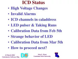
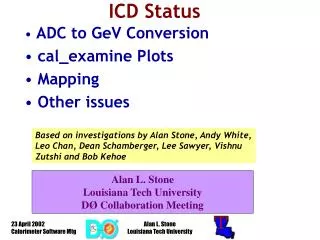
ICD LED Run Status • Purpose • ADC to GeV Conversion • Basics of ICD LED Pulser • Taking Runs • Looking at the data • What’s next? Alan L. Stone Louisiana Tech University
Purpose of LED Runs • Long term monitoring of PMT response • The photomultiplier tubes for the Run II ICD sub-detector were recycled from the Run I ICD boxes • Each channel was individually tuned in order to achieve a mean MIP peak on the cosmic ray test stand • Only lever arm is the high voltage setting • Over a dozen PMTs have already been replaced • About a dozen channels have failed or dropped significantly in gain since the end of the Oct-Nov shutdown • Establish a real world baseline for the full ICD – from scintillator tile to the BLS card • Determine correction for channel to channel variation Alan L. Stone Louisiana Tech University
Interlude borrowed from talk given by Andy White 16 Jan 2002 at Jet Energy Scale Mtg ADC to GeV Conversion • Specific energy loss (dE/dx) in the Bicron BC-400 scintillator (PVT) dE/dxmin= 1.956(g/cm2) 1.032 g/cm3 = 2.02 MeV/cm • Mean MIP peak in test stand ADC counts for 368 channels was 135.7 (aim was 140!) • Relative gain factor between calorimeter preamps (used on the test stand) and the ICD preamps was 3.8. • Extra amplication of 8.7 used to boost signal on test stand • Factor of 10 between least count of test stand ADCs and the calorimeter ADCs. Least count for test stand ADC is 1 mV and calorimeter ADC is 0.1 mV. Alan L. Stone Louisiana Tech University
Interlude continued ADC to GeV Conversion • The cosine factor accounts for angle from normal to an ICD tile relative to a straight line drawn from the IP through the center of a tile. There are three numbers, one for each ieta bin spanned by the ICD: ietacosine factor 12 0.592 13 0.633 14 0.671 NOTE: sampling fractions also include this angular factor, so one must be careful not to apply it twice! • Thickness of all ICD tiles are 0.5 in (about 1.27 cm). Alan L. Stone Louisiana Tech University
Interlude continued ADC to GeV Conversion • Average MIP peak position in calorimeter ADC counts is given by: (135.7 10) / (3.8 8.7) = 41.0 counts • The energy deposition in an ICD tile is given by: (Cal. ADC count / 41.0) (2.02 MeV/cm 1.27 cm) • The result is: (Cal. ADC count 0.06257) [MeV] = (Cal. ADC count / 15982) [GeV] Alan L. Stone Louisiana Tech University
ICD tiles – test stand resultscompiled by Mark Sosebee Alan L. Stone Louisiana Tech University
The Basics of the ICD LED Pulser • Scintillator LED Pulser (SLP) – borrowed from the Muon calibration system • ICD shares VME board with FPD – sits in MCH308 • Accepts external NIM test pulse trigger • VME controlled channel enable, trigger, amplitude and delay • Steve Doulas provided the documentation and expertise! • Excellent GUI created by Marc Hohlfeld! • DC offset resistively coupled to a TTL signal pulse • TTL pulse triggers a transistor which discharges a capacitor into a group of four LEDs • DC offset provides the bias voltage for these LEDs Alan L. Stone Louisiana Tech University
Taking ICD LED Runs • Detailed instructions now part of the Cal Shifters’ Guide (thanks to Florencia for getting cal_elec to work!) • Needs to be given priority during periods without beam • A baseline still needs to be determined • What is the optimum delay time (between 0 and 170 ns)? • What DC offset(s) should be used? • The turn-on voltage as seen on the oscilloscope directly from the electronics is about 6.6 Volts. • The LED pulser needs to be issued a command to turn off during the prepare-for-run-1.1 download • There is currently no alarm to check that the ICD LED pulser is off during global data-taking Alan L. Stone Louisiana Tech University
More on LED Pulser Runs > setup d0online> cd /home/d0icd/vme> ./lmb_int.py & • Voltage is adjustable up to 10.0 Volts in increments of 0.2 Volts • Delay is adjustable from 0 to 170 ns in increments of 2 ns • All Download is preferable – Read feature sets ALL to zero Alan L. Stone Louisiana Tech University
What has been done? • Several LED Runs taken by Pierre Petroff on Jan 23rd • First test of instructions revealed that cal_elec was not working well enough • Stephanie Beauceron took the full set of runs (six DC offsets at six different time delays) on Feb 6th! • Too much work – need to reduce the number of steps • hbook saved files very useful to make plots/printouts offline • Lee Sawyer created SAM datasets • still need more effort offline Ted Elzroth determined ADC count value for one good channel from each Cal Crate in which the ICD is part of the readout - [Crates 0,1,4,5,6,7,10,11]. Did this for each DC offset & time delay setting – 8 6 6 = 288! Alan L. Stone Louisiana Tech University
All ICD channels in Cal Crates 10 & 11 readout Alan L. Stone Louisiana Tech University
ICD in Cal Crate 0 Alan L. Stone Louisiana Tech University
ICD in Cal Crate 1 Alan L. Stone Louisiana Tech University
ICD in Cal Crate 4 Alan L. Stone Louisiana Tech University
ICD in Cal Crate 5 Alan L. Stone Louisiana Tech University
ICD in Cal Crate 6 Alan L. Stone Louisiana Tech University
ICD in Cal Crate 7 Alan L. Stone Louisiana Tech University
ICD in Cal Crate 10 Alan L. Stone Louisiana Tech University
ICD in Cal Crate 11 Alan L. Stone Louisiana Tech University
Next Step • Take another series of runs • Step through delay times of 120-170 ns • Fewer DC offsets: 7.8, 8.2, 8.6 and 9.0 V • Fewer events per run to speed up the process • Do the plots and printouts offline • Why is there a significant timing difference between the ICD channels in different Cal crates? • Possible error? Current method requires strict bookkeeping from the renaming of hbook files to filling the spreadsheet • SLP cable length difference between East & West • Purchase & test new PMTs Alan L. Stone Louisiana Tech University