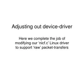
ATLAS Read Out Driver
300 likes | 410 Vues
ATLAS Read Out Driver. Aloisio, Capasso, Della Pietra, della Volpe, Izzo. LHC. L1A. L1Trigger Processor. Off Detector electronics. TTC. L1A. m TCP Intf. Coincidence Matrix & PAD Logic. L1A. RX/SL. ROD. 8. Trigger. Trigger. S-Link to ROB (Read Out Buffer). FIFOs. FIFOs. FIFOs.

ATLAS Read Out Driver
E N D
Presentation Transcript
ATLAS Read Out Driver Aloisio, Capasso, Della Pietra, della Volpe, Izzo
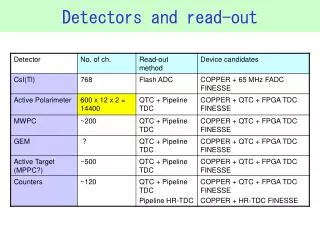
LHC L1A L1Trigger Processor Off Detector electronics TTC L1A mTCP Intf Coincidence Matrix & PAD Logic L1A RX/SL ROD 8 Trigger Trigger S-Link to ROB (Read Out Buffer) FIFOs FIFOs FIFOs RX/SL 8 mTCP Intf ATLAS Read-Out Driver On Detector electronics On detector Electronics execute the trigger algorithm at 40 MHz frequency and send information to the trigger processor, every 25 ns On detector Electronics also elaborate and group the detector’s data. Data are grouped according to the same event number and bunch crossing parameters (Bunch Crossing ID and Level1Accept) and are stored in FIFO memories In occurrence of the L1A signal, data are transferred on optical fiber from the FIFO memories to the OFF Detector electronics; here data are elaborated by the Read Out Driver (ROD) and then sent to the next acquisition levels (Read Out Buffer)
RPC – LVL1 – DAQ Crate • Each RPC DAQ subsystem reads-out data of two of the 64 trigger sectors of the spectrometer • Data arrive at the receiver boards RX-SL on optical fiber and are transmitted to the ROD via the custom backplane RODbus on a High Speed Serial Link (each RX-SL sends 48 bit@40MHz) • Timing signals arriving at the ROD are distributed to the daughter boards over LVDS connections on the custom backplane RODbus • After being elaborated and grouped in a frame, data are sent to the Read Out Buffer
The custom backplane RODbus ROD µTCPI µTCPI RX/SL Plug-in on VME64x backplane Central connector for ROD Slot 2 and 4 for RX-SL Slot 1 and 5 for µTCP Interface Upper connectors for LVDS data (~2.2 Gbit/s) Lower connectors TTL for controls (busy, reset, diagnostics) Temperature sensor and ADC for power supply controls The RODbus has been successfully tested and is already installed
RPC ROD Functionality The ROD is “interface” between the RPC LVL1 Trigger Readout and the DAQ The ROD: - receives the TTC synchronization signals and re-distribute them via the RODbus to the RX/SL and μTCPI - handles the Busy Signal exchanged with μCTPI - readout data from RX/SL via the RODbus - formats the data according DAQ specification and sends them to the ROS via optical fiber (SLINK)
RPC ROD Data Format • The ROD does the a local Event building of the data at Crate Daq Level. • The data are formatted according to the ATLAS raw event format • The ROD event building packs the data readout from the RX/SL in frame starting with an header block composed by 9 long word (Source ID, BunchID LVL1 ID, etc ) and an footer of 3 long word • The data read-out from the RX/SL are packed according a similar schema, in which the fragment coming from different sources are packed in fragment starting with an header and a footer • The RX/SL Data are 16 bit words packed in 32 bit word. This means that some word are needed to re-align the data frames. • It performs LVL1 ID and Bunch ID alignment checks between the trigger information coming from central trigger processor and the ones coming from the front-end electronics • It also does some overall data integrity checks (missing data from one or both RX within a timeout window; JUMBO size fragments; etc.. )
The ROD architecture Power Supply analog monitoring •The VME FPGA allows the communication with the VMEbus, with the microcontroller and with the receiver of the TTC •The ROD FPGA is interfaced with the RODbus and with the RX-SL boards via the SerDes receivers •The two FPGAs communicate via a custom serial protocol •Data are sent to the Read Out Buffers through the S-Link transmitter RS232 16 uP 2 VME FPGA 64 VMEbus I2C TTCrq 1 4 4 + 4 (LVDS) 1 ck SerDes 9 4 ROD FPGA S-Link 32 RODbus 8 32 ck SerDes 9 32
RX Header L1A BCID Data RX Footer RX Header L1A BCID Data RX Footer MUON ROD FRAME L1A = xxxx Serial data in Serial data out Event Building: block diagram L1A, BCID Controls out L1A, BCID FIFO Mux S-Link interface Controls in Trigger Type Strobe SLink Clock TTCIntf. Controls 512 x 36 40 MHz Trig. Type TTC Clock 4k x 32 FIFO Mux To S-Link FIFO 512 x 36 Mux Event Builder Engine FIFO RX data FIFO Mux Write Enable RX Clock 4k x 32 SerDes Intf. 4k x 32 RX data Write Enable RX Clock FIFO Mux 4k x 32 40 MHz x2 DLL Control Logic Board Clock Configuration Register File RODbus Interface Synchronous Serial Link to/from VME FPGA
RX Header L1A BCID Data RX Footer RX Header L1A BCID Data RX Footer MUON ROD FRAME L1A = xxxx Serial data in Serial data out Event Building: clock domains L1A, BCID L1A, BCID FIFO Mux Controls S-Link interface Trigger Type Strobe TTCIntf. Controls 40 MHz SLink Clock Trig. Type TTC Clock FIFO Mux FIFO Mux Event Builder Engine FIFO RX data FIFO Mux Write Enable RX Clock SerDes Intf. RX data Write Enable RX Clock FIFO Mux 40 MHz x2 DLL Control Logic Board Clock Configuration Register File RODbus Interface Synchronous Serial Link
RX Header L1A BCID Data RX Footer MUON ROD FRAME L1A = xxxx MUON ROD FRAME L1A = xxxx The data path Power Supply analog monitoring •TTC managed via I2C protocol by the microcontroller RS232 16 uP 2 VME FPGA 64 VMEbus I2C •Timing signals (clock, L1A, synchronization) are received by the ROD FPGA and are distributed on the RODbus to the RX/SLs TTCrq 1 4 4 + 4 (LVDS) 1 ck SerDes 9 •RX/SL frames arrive at the ROD FPGA via RODbus, through the SerDes, and are used to build the ROD frame 4 ROD FPGA S-Link 32 RODbus 8 32 ck SerDes 9 32 • Event monitoring and system status can be checked via VME
RX Header L1A BCID Data RX Footer no SerDes Fifos empty ? yes no Timeout ? Parse RX frame yes Error handling procedure continue The Event Building algorithm (1) yes • The builder engine waits for a L1A signal to process data • Then starts writing Header in the output FIFO (SLink, VME or both) L1A Fifo empty ? no Write ROD header ROD Header L1A = xxxx • The engine waits for data arriving from the RX boards, stored in SerDes FIFOs •RX frames retrieved from SerDes FIFOs are parsed to find header and L1A • If data are not available from RX boards within a programmable time window, an error handling procedure is started
continue no Error handling procedure RX Header L1A BCID Data RX Footer RX Header L1A BCID Data RX Footer write ROD footer yes MUON ROD FRAME L1A = xxxx L1A Fifo empty ? ROD Footer no The Event Building algorithm (2) RX frames correct ? yes append RX frames • If the RX frame is correctly formatted and the embedded L1A matches the current one, it is appended to the ROD frame • The ROD Frame is closed by a specific footer with keywords, word count and error flags • An error procedure is started elsewhere
RX Header L1A BCID Data ....... Data ......... RX Header L1A BCID Data ....... ....... ....... Data RX Footer ......... ........ BCID Data ....... Data RX Footer Skipped data Skipped data RX Header L1A BCID Data ....... Data RX Footer RX Header L1A BCID Data ....... Data RX Footer RX Header L1A BCID Data ....... Data RX Footer Event Building: syntax error •JUMBO Frame: frames greater than the maximum allowed length Maxlength. Realignment at next Header. ErrorFlag •RX Frame incomplete: RX Frame Footer missing. Realignment at next Header. ErrorFlag •RX Frame corrupted: RX Frame Header missing. Search for next valid Header
The ROD microcontrolled • Microcontroller data can be read by RS232 and by VME • The ARM7 microcontroller allows us to monitor the power supply on the ROD board , on the backplane and to access via I2C to all the TTCrx registers
ROD Test in Naples • Stand-Alone test in Naples • ELECTRICAL TESTS • FUNCTIONAL TESTS • FPGA’s Firmware • Microcontroller • TTC receiver • Busy handling (send to MUCTPI) • Data transfer RODROS via SLINK • ROD Crate functional Test • Data Readout of RX/SL via RODBus • EVENT BUILDING • Only random data packet in RX/SL fifos • Loading of pre-built data packets in RX/SL fifos (Walking bit RX/SL, Empty Packet, Simulated data packet) Test procedure still to be finalized
Status - Hardware • 10 RODs already at CERN • 1 pre-series to be replaced + 9 Final version • 32 RODs delivered in Naples in November (spares are coming). • Test started upon delivery • Regular shipment at CERN in the coming weeks • Tests & shipment at CERN will finish within first half of 2008
Status – Software • A complete low-level VME API Library and Scripts to operate and configure the ROD are ready and used in test bed since long. • A First Prototype of the Final FSM for RPC RCD is ready and successfully tested during Muon Combined Cosmic Runs in the week 3-9 Dec. • ROD DAQ software fully integrated in the ATLAS DAQ system. • Data Channel For data sampling (monitoring) still to be debugged.
ROD in ATLAS runs • As of friday we managed to run the system • 10 RODs on 6 different crates sending data to the ATLAS ROS. The data trasfer from ROS to the Event builder was done through TCP/IP. • Many noise runs taken smoothly • We generate LVL1 triggers using an external clocks that is sent to the whole chain (ROD, SL/RX, TTC,etc ) and we acquire the chamber with HV on (noise run) • We took smoothly a noise run of about 200K evts at a trigger rate of 180 Hz • We than tried to raise up the clock frequency up to 180 kHz. The TCP/IP limited the bandwidth but there were no problem in the event building nor data corruption • Several comsmic runs in both stand-alone or combined with other subdetectors. • About few millions of cosmics stored in 1 week @ 200 Hz of trigger rate • ECR and BCR signals handled in the correct way • Deeper data analyses are ongoing
Cosmics with RODs • Qui inserirò un paio di plot con I cosmici acquisiti con il ROD e statistiche sugli errori di formato dei dati.
ATLAS RPC & LVL1 Online Monitoring Canale, Della Pietra, della Volpe
Online Monitoring • Based on GNAM framework and fully integrated in the ATLAS Online MOnitoring group. • Custom RPC Data Decoding library • Custom Mapping scheme between elx channels and physical strips (40% done) • Operational since 2004 Combined test beam
RPCGnam Online Monitoring Coincidence between eta and phi strips on the same chamber for each plane in the muon specrometer. RPC time with respect to LVL1 signal for each chamber
RPCGnam Online Monitoring Difference between BCID of the ROD fragment and all sub-fragments (RX, PAD, CM, SL) Data fragment consistency in the RPC readout
RPC Gnam Online Monitoring • Open issues • Complete the mapping files for all the sectors • Better organization of OKS Segments • Selection of histograms to be sent to the DQMF and definition of checking algorithms. • Porting of the offline analysis into the online framework: • Clusters • Geometry • Fast tracking • Combined Online Monitoring with MDTs
ATLAS Data Quality and Commissioning with cosmics Biglietti, Canale, Conventi,Della Pietra, della Volpe, Toglia
Offline Data Quality with cosmics RUN 20504 Cluster size of RPC Hits for each plane Cluster size
RUN 20504 Y (cm) Z (cm) Offline Data Quality with cosmics Napoli group Simple Geometry description of the RPC in the muon spectrometer
Offline Dat Quality with cosmics RUN 20504 Phi angle RPC standalone 3D tracking Direction of muons recontructed in Barrel A Direction of muons recontructed in Barrel C Theta angle Biggest shaft seen from different point of view