Download
1 / 19
190 likes | 314 Vues
This document outlines the specifications for the read-out PCB, detailing the process, material descriptions, and tolerances. It includes a comprehensive modification history, highlighting changes such as misalignment tolerances for the resistive layer, copper thickness adjustments, and accuracy requirements for board cutting and drilling. Key sections include process descriptions, PCB and flex specifications, gluing methods, and pillar creation. The document is under the responsibility of Rui De Oliveira, and any modifications must be approved by him.

E N D
NSW Read-out spec Rev:B Rev:B ( check-->19 pages document)
Modification history • Rev: A date: 4 December 2013 • Rui : Creation of the document (19 pages) • Rev: B date: 6 January 2014 • Rui : the misalignment tolerance for the resistive layer is added • Rui: the starting copper thickness is changed • Rui : The board cutting accuracy is added • Rui: The board drilling accuracy is added Document under the responsibility of Rui De Oliveira , no modification is allowed. Any request for modification should be sent to Rui De Oliveira (rui.de.oliveira@cern.ch) . The active document and all the previous revisions are stored in TE/DEM/EM/PMT data base. If you use this document for production purpose please contact Rui de Oliveira to know the active version. Rev:B ( check-->19 pages document)
Chapters 1/Process description 2/PCB detailed description 3/Flex description 4/Gluing description 5/Pillar creation 6/files Rev:B ( check-->19 pages document)
Chapter1:Process description Rev:B ( check-->19 pages document)
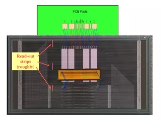
50um Kapton + resistive strips PCB + readout strips Rev:B ( check-->19 pages document)
50um Kapton + resistive strips PCB + readout strips 25um Glue Rev:B ( check-->19 pages document)
50um Kapton + resistive strips PCB + readout strips 25um Glue Isostatic Gluing Rev:B ( check-->19 pages document)
50um Kapton + resistive strips PCB + readout strips 25um solid Glue High temp Gluing Pillars creation Rev:B ( check-->19 pages document)
Chapter 2:PCB detailed description Rev:B ( check-->19 pages document)
PCB: -2250mmx 500mm ???? -single side -0.5mm thick +/- 10% -Starting copper foil : 17um thick copper + 17um or 35um copper protection -Final copper thickness 17um -Pattern absolute accuracy: +/-30um referring to the GERBER file in the 50cm side +/-120um referring to the GERBER file in the 2m side -120um minimum line and space , +/-20% general accuracy -NI/Au or Ag plating on connector fingers -Cutting absolute position accuracy : +/-50um referring to the copper pattern on the 50cm side +/-200um referring to the copper pattern on the 2m side -Cutting relative accuracy : (not referred to the pattern) +/-50um in all directions -Drilling absolute position accuracy : +/-50um referring to the copper pattern on the 50cm side +/-200um referring to the copper pattern on the 2m side -drilling relative accuracy : (not referred to the pattern) +/-50um in all directions PCB + readout strips Base material, when used, shall be flame retardant rated UL 94V-0 laminate glass fiber epoxy and conform to L94 according to IPC-4101/94. Copper shall be type H with pits and dent, class B. When procuring base material the following are required: minimum TG 170°C, minimum TD(5%) 350°C, minimum T-288 35min, maximum Z-axis thermal expansion coefficient above TG 280PPM/°C (alternatively Z-axis thermal expansion coefficient between 50-260°C of 3.5% maximum is acceptable) Acceptance of finished printed boards shall be in accordance with IPC-A-600, class 2 Fabrication and inspection shall be according to IPC-6011 and IPC-6012, class 2 Rev:B ( check-->19 pages document)
Chapter 3:Flex description Rev:B ( check-->19 pages document)
Flex: -2250mmx 550mm ????? -single side -50um thick +/- 1um -silk screen printed or deposited resistor on top -Kapton HN substrate -400um min line -100um min space - Visual inspection IPC-A-600 Class 2 50um Kapton + resistive strips Rev:B ( check-->19 pages document)
Chapter 4:Gluing description Rev:B ( check-->19 pages document)
Gluing Stack up SS main spacer 2mm mini Pacopad Aluminium 0.3mm Pacothane Flex 25um glue (KrempelAkaflex CDF 25) PCB Pacothane Aluminium 0.3mm Pacopad SS main spacer 2mm mini Rev:B ( check-->19 pages document)
Gluing parameters • Pressure: 30kg/cm2 • Ramp up temp: max 10deg/min • Polymerization time and temp: 45 min @ 170deg • Ramp down temp: max 10deg/min • Misalignment max: 0.06 degrees in strip direction • corresponding to max 1mm shift over 2.2m • Misalignment in the other axis 3mm max Rev:B ( check-->19 pages document)
Chapter 5:Pillar creation Rev:B ( check-->19 pages document)
Pillars: -300um pillars diameter -128um +/- 2um height -2 layers of Pyralux PC 1025 -Final curing min 160deg 1 Hour -Ramp up curing : max 50 deg / hour Rev:B ( check-->19 pages document)
Chapter 6:Files Rev:B ( check-->19 pages document)
Files • Top copper strips: • Xxxx • Xxxx • Kapton area: • Xxxx • xxxx • Resistive layer: • Xxxx • Xxxx • Pillar layer: • Xxxx • Xxxx • Cutting file: • Xxxx • Xxxx • Drilling file: • Xxxx • Xxxx Rev:B ( check-->19 pages document)