Download
1 / 35
350 likes | 479 Vues
This chapter provides an in-depth look at Frame Relay and Asynchronous Transfer Mode (ATM) as alternatives in Wide Area Networks (WAN). It discusses their architecture, operation, and key features, highlighting the efficiency of Frame Relay over X.25 and ATM's higher data rates. The control and user planes are examined, along with congestion control strategies and the advantages of virtual paths and channels. This comprehensive analysis aids in understanding the characteristics and benefits of these significant technologies in data communications.

E N D
Chapter 13:Frame Relay & ATM Business Data Communications, 6e
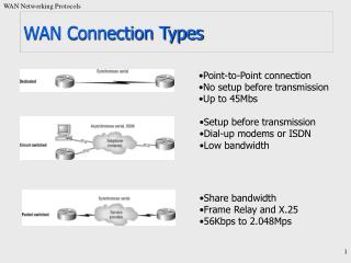
X.25 Key Features • Call control packets carried on the same channel and same virtual circuit as data packets. • Multiplexing of virtual circuits takes place at layer 3. • Both layer 2 & 3 include flow and error control mechanisms
Frame Relay Key Features • Designed to be more efficient than packet switching • Designed to eliminate excessive X.25 overhead • Call control signalingis on a separate logical connection from user data. • Multiplexing and switching of logical connections takes place at layer 2. • No hop-by-hop flow control and error control.
Frame Relay Characteristics • Control signaling takes place on a separate logical connection (nodes don’t need state tables for each call) • Multiplexing/switching take place at layer 2, eliminating a layer of processing • No hop-by-hop flow/error control
Frame Relay vs. X.25 • Reliability • Frame relay loses ability to do link-by-link flow and error control. • X.25 link level protocol provides reliable hop-by-hop link control • With increasing reliability of transmission and switching facilities, this is not a major disadvantage. • Streamlining • Frame relay reduces need for protocol functionality at the user-network interface, and reduces internal network processing • Improvement in throughput using frame relay, compared to X.25, of an order of magnitude or more
Frame Relay Control Plane • Similar to common channel signaling, in that a separate logical channel is used for control information. • At the data link layer, LAPD (Q.921) provides a reliable data link control service, with error control and flow control, between user (TE) and network (NT). • This data link service is used for the exchange of Q.933 control signaling messages.
Frame Relay User Plane • User-plane protocol is LAPF (Link Access Procedure for Frame Mode Bearer Services), defined in Q.922 • Core functions of LAPF are used for frame relay: • Frame delimiting, alignment, and transparency • Frame multiplexing/demultiplexing using address field • Inspection of frame contents • Inspection of the frame to ensure that it is neither too long nor too short • Detection of transmission errors • Congestion control functions
User Data Transfer • No control field; connection mgt must be carried out on a separate channel, and there is no flow or error control • Flag and frame check sequence (FCS) fields function as in HDLC. • Information field carries higher-layer data • Address field length determined by the address field extension (EA) bits
Frame Relay Call Control • Establish a logical connection between two endpoints, and assign a unique DLCI to the connection • Exchange information in data frames. Each frame includes a DLCI field to identify the connection • Release the logical connection
Frame Relay Congestion Control • Two strategies supported in frame relay • Congestion avoidance procedures are used at the onset of congestion to minimize the effect on the network • Congestion recovery procedures are used to prevent network collapse in the face of severe congestion
Congestion Notification Bits • Backward Explicit Congestion Notification (BECN): Indicates that the frame that the user transmits on this logical connection may encounter congested resources. • Forward Explicit Congestion Notification (FECN): Indicates that the frame has encountered congested resources.
Asynchronous Transfer Mode (ATM) • Also known as cell relay • Faster than X.25, more streamlined than frame relay • Supports data rates several orders of magnitude greater than frame relay • Data on logical connection is organized into fixed-size packets, called cells. • No link-by-link error control or flow control.
Virtual Channels & Virtual Paths • Logical connections in ATM are virtual channels • analogous to a virtual circuit in X.25 or a frame relay logical connection • used for connections between two end users, user-network exchange (control signaling), and network-network exchange (network management and routing) • Variable rate, full duplex flow is exchanged • A virtual path is a bundle of virtual channels that have the same endpoints.
Advantages of Virtual Paths • Simplified network architecture • Increased network performance and reliability • Reduced processing and short connection setup time • Enhanced network services
Virtual-Path/Virtual-Channel Characteristics • Quality of service • Switched and semi-permanent virtual-channel connections • Cell sequence integrity • Traffic parameter negotiation and usage monitoring
ATM Control Signaling:Virtual Paths • Semipermanent virtual channels may be used for user-to-user exchange; no control signaling is required. • Meta-signaling channel, a permanent low-data-rate channel used for a virtual channel that can be used for call control • user-to-network signaling virtual channel can than be used to set up virtual channels to carry user data • can also be used to set up a user-to-user signaling virtual channel within a preestablished virtual path
ATM Control Signaling:Virtual Paths • A virtual path can be established on a semipermanent basis by prior agreement. No control signaling is required. • Establishment/release may be customer controlled. Customer uses a signaling virtual channel to request the virtual path from the network. • Establishment/release may be network controlled. Network establishes a virtual path (may be network-to-network, user-to-network, or user-to-user)
ATM Cell Fields • Generic Flow Control (GFC) is used for control of cell flow only at the local user-network interface, to alleviate short-term overload conditions in the network. • Virtual Path Identifier (VPI) field constitutes a routing field for the network. • Virtual Channel Identifier (VCI) field is used for routing to and from the end user. • Payload Type (PT) field indicates the type of information in the information field. • Cell loss priority (CLP) bit is used to provide guidance to the network in the event of congestion. • Header Error Control (HEC) field is used to correct and detect errors in the header
ATM Service Categories • Real-Time Service • Constant bit rate (CBR) • Real-time variable bit rate (rt-VBR) • Non-Real-Time Service • Non-real-time variable bit rate (nrt-VBR) • Available bit rate (ABR) • Unspecified bit rate (UBR) • Guaranteed frame rate (GFR)
Real Time Service • Constant Bit Rate (CBR)- simplest service to define- used by applications that require a fixed, continuously available data rate- commonly used for uncompressed audio and video
Real Time Service • Real-Time Variable Bit Rate (rt-VBR)- intended for time sensitive applications- transmits at a rate that varies with time- can be bursty
Non-Real Time Services • Non-Real Time Variable Bit Rate (nrt-VBR)-end system specifies a peak cell rate, sustainable cell rate and how bursty the cells may be- network allocates resources to provide low delay and minimal cell loss
Non-Real Time Services • Unspecified Bit Rate (UBR)-suitable for TCP based traffic -cells are forwarded on a FIFO basis-delays and variable losses are possible-used for text/image/data transfer, messaging, distribution, retrieval and remote terminal
Non-Real Time Services • Available Bit Rate (ABR)-specifies a peak and minimum cell rate -network resources are allocated to at least the minimum level-used for LAN interconnections
Non-Real Time Services • Guaranteed Frame Rate (GFR)-designed to support IP backbone subnetworks.-seeks to optimize frame-based traffic from a LAN through a router onto an ATM backbone