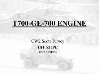
T700 ENGINE
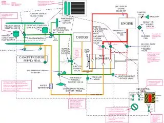
T700 ENGINE. T700 ENGINE – LEFT HAND SIDE. ACTUATOR/CRANKSHAFT ASSEMBLY FOR VARIABLE GEOMETRY SYSTEM. AISBV Actuates automatically to provide bleed functions at approx 88-92% Ng or 30% Tq Will open below 88-92% Ng and close above. IPS. THERMO-COUPLE HARNESS (TGT). FUEL INJECTORS(12).

T700 ENGINE
E N D
Presentation Transcript
T700 ENGINE – LEFT HAND SIDE ACTUATOR/CRANKSHAFT ASSEMBLY FOR VARIABLE GEOMETRY SYSTEM • AISBV • Actuates automatically to provide bleed functions at approx 88-92% Ng or 30% Tq • Will open below 88-92% Ng and close above IPS THERMO-COUPLE HARNESS (TGT) FUEL INJECTORS(12) IGNITORS(2) FRONT Eng Inlet Anti Ice Port Eng Anti-Ice • ECU: • Np Governing to maintain constant Power Turbine and Rotor RPM • Load Share Comparator(keeps tq within 5% by adjust low eng Np up to 3% • TGT Limit Amplifier(limits TGT to 834-852 deg), inop during Eng Start, Lockout, Compressor Stall and Alternator Failure • Tq Motor Amplifier – actuates Tq Motor in HMU to bias metering valve and also receives feedback signal from Linear Variable Differential Transducer in HMU • NpOverspeed Switch to actuate Overspeed Solenoid – backup power from AC Primary Bus • History Recorder – records TGT and Ng and is used to track life of GG and IPS (backup power from AC Primary Bus) • Conditioning and Transfer to cockpit of Tq and Np Signals. • Np Reference for Np Trim Switch 96-101% with Pilot Side having authority Np SENSOR
OIL PUMP • 6 Scavenge Elements • 1 Pressure Element OIL FILTER BYPASS SWITCH( >80 PSI) • OIL FILTER • *44-60PSI filter button pops • 60-80PSI = light in cockpit • >80PSI will actually bypass * Oil Filter Impending Bypass button deactivated below 38 deg) • OIL TEMP/ PRESSURE SENSE (NOT VISIBLE) • Pressure Light on at 20 PSI • Temp Light on at 150 deg C COLD OIL RELIEF Filter Cooler CHIP DETECTOR (OIL) - no Fuzz burn 4. OIL COOLER • ALTERNATOR • -1 Winding for Ng Signal • 1 Winding for ECU Power • 1 Winding for Engine Ignition FUEL FILTER BYPASS SWITCH(18-22 PSI) • HISTORY DATA RECORDER • Records TGT and Ng. • Backup power from AC Primary Bus 1. ENG DRIVEN FUEL PUMP(45-90 PSI) 2. FUEL FILTER GREEN – Engine to airframe interface BLUE – Np Overspeed and Tq Indication systems YELLOW – Engine Electrical Functions BLACK – Engine Ignition 5TH STAGE AIR FOR ENG ANTI - ICE SWIRL FRAME -Initial Stage of air purification RIGHT LEFT • ENGINE FUEL FLOW • 1 Eng Driven Fuel Pump • 2 Fuel Filter • 3 HMU(next page) • 4 Liquid to Liquid Oil Cooler • 5 POU(next page) T700 ENGINE – FRONT VIEW
IPS • Swirl Frame on eng inlet directs contaminated air to outside of eng inlet. 85% of inlet air travels direct to compressor. Other 15%(dirty) is directed to IPS. • Use centrifugal force to separate heavy, contaminated particles. Dirty Air dumped overboard. • Mechanically driven by AGB • Not effective at low Ng or on Sheet Ice Shed from Windshield due to Ady Qualities of the ice. • 3. HMU • Pumps Fuel via high pressure Vane Pump(400-832 PSI) • Meters Fuel via PAS, LDS and ECU. ECU inputs actioned by Tq Motor inside HMU) • Controls VG and VIGV’s via Actuator Shaft • Controls AISBV via Actuator Shaft • Limits Accel and Decel of engine to prevent Compressor Stall/Flameout • Controls Vapor Vent for Manual Fuel Prime • Allows PAS over-ride by mechanically passing all Tq Motor Inputs when PCL advanced full forward ie ECU Lockout PNEUMATIC STARTER -30,000 rpm at max Ng -Driven by APU, Other Engine or Ext Source. - Eng Start Valves air actuated, elec controlled • 5. POU • Meters Start Fuel (outlet to Start Fuel Manifold and 2 primer nozzles) • Meters Main Fuel Flow(outlet to main fuel manifold and 12 injectors) • Purges(via P3 air) Start, Main fuel manifolds as well as injectors and primers(outlet overboard) • On command from ECU limits fuel flow to prevent Np Overspeed(106+/-1%) • PAS • Sets max pwr avail sched. • Set max pwr limits that may never be exceeded by Collective. • LDS • Adjust Load Demand schedule. • Adjusts fuel flow simultaneously with Coll TQ and O/S SENSOR -sends signal to ECU for conditioning then to SDC and cockpit -O/S signal used by ECU to adjust POU Np SENSOR -sends signal to ECU for conditioning then to SDC and cockpit LEFT RIGHT T700 ENGINE – REAR VIEW
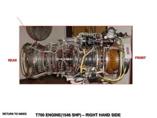
TGT (T4.5) Thermocouples(7) 0-775 Deg C Normal 775-850 Deg 30 min Limit 850 deg – Start Abort 850 – 886 deg 12 Sec Limit • Centrifugal Compressor • Single Stage - 5th Stage Air(P3) • air for AISBV • air for Eng Inlet Anti Ice • Air for Pneumatic Manifold(X-bleed Start) • Air for purging • Air for Cockpit Heat and ERFS • Pneumatic Starter • for X-bleed start must have min 90%Ng, 100%Np and Eng Anti Ice Light Off. • At least 60 sec b/n each start cycle • 15 deg C and below • 2 consecutive start followed by 3 min rest then 2 addn starts followed by 30 mins • Above 15 deg C • -2 consecutive start cycles followed by 30 min rest • COMBUSTION LINER • 12 FUEL INJECTORS • 2 PRIMER NOZZLES • 2 IGNITORS PAS LDS FRONT REAR TQ Sensor 0 –100% Dual Cont 0 – 110% Single Cont 100-125% Dual 12 Sec Transient 110-135% Single 12 Sec Transient NpOverspeed Sensor – 106+/-1% Np Turbine Min 91% except idle/transient 95-101% Cont 101-105% Transient 105-107% 12 Sec Transient (avoid 20-40 and 60-90%) -2 STAGE -100% = 20900RPM -Uses 25% of combustion energy NG Turbine 0-99% Cont 99-102% 30 min 102-105% 12 sec -2 STAGE -29000 (idle 63%) –44700 RPM (100%) -Uses 75% of combustion energy • Axial Compressor • -5 STAGE • Comp Ratio of Axial Comp 7:1 • Comp ratio of both Axial and Centr 17:1 T700 ENGINE(1546 SHP) – RIGHT HAND SIDE