An Introduction to Atomic Force Microscopy
An Introduction to Atomic Force Microscopy. Peter Grutter Physics Department www.physics.mcgill.ca/~peter/. 1 . Introduction 2. Magnitude of forces How to measure forces Ultimate limits 3. Components of an AFM Cantilever Deflection sensing Feedback Piezo scanners


An Introduction to Atomic Force Microscopy
E N D
Presentation Transcript
An Introduction to Atomic Force Microscopy Peter Grutter Physics Department www.physics.mcgill.ca/~peter/ BIMR Wokshop, May 15th, 2002
1. Introduction 2. Magnitude of forces How to measure forces Ultimate limits 3. Components of an AFM Cantilever Deflection sensing Feedback Piezo scanners Image processing Approach mechanisms 4. What forces? Repulsive forces van der Waals forces Electrostatic forces Magnetic forces Capillary forces 5. Operation modes Normal and lateral forces Force spectroscopy Modulation techniques AC techniques Dissipation 6. Imaging artifacts 7. Summary Outline BIMR Wokshop, May 15th, 2002
Scanning Tunneling Microscope (STM) • Based on quantum mechanical tunneling current • Works for electrically conductive samples • Imaging, spectroscopy and manipulation possible D. Eigler, IBM Almaden BIMR Wokshop, May 15th, 2002
Bonding energies: Quantum mechanical (covalent, metallic bonds): 1-3 nN Coulomb (dipole, ionic): 0.1-5 nN Polarization (induced dipoles): 0.02-0.1 nN J. Israelachvili ‘Intermolecular and Surface Forces’Academic Press ‘Back of the envelope’: Atomic energy scale: Ebond ~ 1-4 eV ~ 2-6 • 10-19 J Typical bonding length: a ~ 0.2 nm Typical forces: F = E/a ~ 1-3 nN Forces between atoms BIMR Wokshop, May 15th, 2002
Dz spring constant k Harmonic oscillator: f2 = k/m F’ acts like a spring in series: f2 = (k+F’)/m Measuring forces Force: F = kDz Force gradient F’ : F’= 2k Df/f approximation good if d2V / dz2 = constant otherwise: Giessibl, APL 78, 123 (2001) BIMR Wokshop, May 15th, 2002
Ultimate limits of force sensitivity 1. Brownian motion of cantilever! thermal limits Martin, Williams, Wickramasinghe JAP 61, 4723 (1987) Albrecht, Grutter, Horne, and Rugar JAP 69, 668 (1991) D. Sarid ‘Scanning Force Microscopy’ 2. Other limits: - sensor shot noise - sensor back action - Heisenberg D.P.E. Smith RSI 66, 3191 (1995) T=4.5K A…rms amplitude A2 = kBT/k Roseman & Grutter, RSI 71, 3782 (2000) Bottom line: Under ambient conditions energy resolution ~ 10-24J << 10-21J/molecule BIMR Wokshop, May 15th, 2002
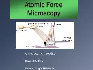
Atomic Force Microscope deflection sensor approach force sensor tip feedback sample vibration damping scanner Data acquisition BIMR Wokshop, May 15th, 2002
The force sensor Microfabrication of inte-grated cantilevers with tips BIMR Wokshop, May 15th, 2002
W L t Spring constants k and resonant frequency f of cantilevers Spring constant k : typical values: 0.01 - 100 N/m Young’s modulus EY ~ 1012 N/m2 Resonant frequency fo: typical values: 7 - 500 kHz BIMR Wokshop, May 15th, 2002
Calibration of cantilever spring constant k Methods: • Thermal Hutter and Bechoefer, RSI 64, 1068 (1993) • Sader method (measure geometry) Sader RSI 66, 9 (1995) • Reference spring method M. Tortonese, Park Scientific • Added mass Walters, RSI 67, 3583 (1996) Excellent discussion and references: www.asylumresearch.com/springconstant.asp BIMR Wokshop, May 15th, 2002
D Giessibl, APL 73, 3956 (1998) Deflection sensors A A) Beam deflection B) Interferometry C) Piezoresisitive D) Piezoelectric Meyer and Amer, APL53, 1045 (1988) B Rugar et al., APL 55, 2588 (1989) BIMR Wokshop, May 15th, 2002
Feedback modes F = constant z = constant BIMR Wokshop, May 15th, 2002
+x -x -y Piezoelectric scanners (1) Properties: 1. Hysterisis (non-linear) 2. Creep (history dependent) 3. Aging (regular recalibration) (2) Piezo tube +y BIMR Wokshop, May 15th, 2002
Creating an image from the feedback signal line scan gray scale image processed image BIMR Wokshop, May 15th, 2002
Image processing Beware of introducing image processing artifacts ! Understand and know what you are doing Processing (here ‘flatten’) can remove them, but can create new artifacts. Raw data shows ‘jumps’ in slow scan direction. (Due to pointing instabilities of laser). BIMR Wokshop, May 15th, 2002
Fixed point Micrometer screw 1 Micrometer screw 2 Tip-sample approach • Dynamic range from mm to nm • Coarse & fine approach! • Many possibilities: 1. Lever arms 2. Piezo walkers BIMR Wokshop, May 15th, 2002
And finally: thermal drift! Touching the microscope (e.g. sample, cantilever) will change its temperature T. Shining light on it too! Cantilever has a mass of ~ 1 ng, and thus a VERY small heat capacity. So what!?! DL/L = constDT const ~ 10-5 BIMR Wokshop, May 15th, 2002
The first AFM G. Binnig, Ch. Gerber and C.F. Quate, Phys. Rev. Lett. 56, 930 (1986) BIMR Wokshop, May 15th, 2002
Repulsive Contact Forces Rubbed Nylon LCD alignment layer Diblock co-polymers used as self assembled etch mask Meli, Badia, Grutter, Lennox, Nano Letters 2, 131 (2002) Ruetschi, Grutter, Fuenfschilling and Guentherodt, Science265, 512 (1994) BIMR Wokshop, May 15th, 2002
Van derWaals forces FvdW = AR/6z2 A…Hamaker const. R…Tip radius z…Tip - sample separation A depends on type of materials (polarizability). For most materials and vacuum A~1eV Krupp, Advances Colloidal Interface Sci. 1, 113 (1967) R~100nm typical effective radius -> FvdW ~ 10 nN at z~0.5 nm BIMR Wokshop, May 15th, 2002
Electrostatic forces Felectrostatic = p e0 RU2/ z U…Potential difference R…Tip radius z…Tip - sample separation R~100nm typical effective radius U=1V -> Felectrostatic ~ 5 nN at z~0.5 nm Tans & Dekker, Nature404, 834 (2000) BIMR Wokshop, May 15th, 2002
Chemical forces Si(111) 7x7 FMorse = Ebond/z • (2e-k(z-s) - e-2k(z-s)) Ebond …Bond energy k …decay length radius s…equilibrium distance Other popular choice: 12-6 Lennard Jones potential Lantz et al, Science 291, 2580 (2001) BIMR Wokshop, May 15th, 2002
Magnetic Forces Fmagntic = mtip • Hsample Comprehensive review: Grutter, Mamin and Rugar, in ‘Scanning Tunneling Microscopy II’ Springer, 1991 Melting of flux lattice in Nb Images stray field and thus very useful in the magnetic recording industry, but also in science. Roseman & Grutter, unpublished BIMR Wokshop, May 15th, 2002
Magnetic Force Microscopy Tracks on Magnetic reversal studies by MFM particles size 90 x 240 x 10 nm X. Zhu (McGill) hard disk floppy disk image size 10 and 30 micrometers. M. Roseman (McGill) BIMR Wokshop, May 15th, 2002
Tip Water Surface Capillary forces (water layer) Total force on cantilever = sum of ALL forces There is always a water layer on a surface in air! Fcapillary = 4p R g cos g …surface tension, ~10-50 mJ/m2 …contact angle Can be LARGE (several 1-10 nN) BIMR Wokshop, May 15th, 2002
Different operation modes • Imaging (DC) • Lateral or frictional forces • Force spectroscopy (F(z), snap-in, interaction potentials, molecular pulling and energy landscapes) • Modulation techniques (elasticity, electrical potentials, …) • AC techniques (amplitude, phase, FM detection, tapping) • Dissipation BIMR Wokshop, May 15th, 2002
DC Imaging, lateral forces Diblock co-polymer: Normal forces Friction Meli, Badia, Grutter, Lennox, Nano Letters 2, 131 (2002) BIMR Wokshop, May 15th, 2002
Snap in condition: k <F’ force For meaningful quantitative analysis, k > stiffness of molecule distance a water a Force Spectroscopy BIMR Wokshop, May 15th, 2002
W(111) tip on Au(111) Cross et al. PRL 80, 4685 (1998) Schirmeisen et al, NJP 2, 29.1 (2000) Field ion microscope manipulation of atomic structure of AFM tip BIMR Wokshop, May 15th, 2002
Site specific chemical interaction potential: Si(111) 7x7 Lantz, Hug, Hoffmann, van Schendel, Kappenberg, Martin, Baratoff, and Guentherodt , Science 291, 2580 (2001) BIMR Wokshop, May 15th, 2002
AFM Elasticity Maps of Smooth Muscle Cells Induced contraction elasticity contrast topography Cells stiffness increased B. Smith, N. Durisic, P. Grutter, unpublished HANKS buffer 1mM serotonin HANKS buffer no serotonin BIMR Wokshop, May 15th, 2002
DNA “Unwinding” Anselmetti, Smith et. al. Single Mol. 1 (2000) 1, 53-58 AFM probe Au surface Nature - DNA replication, polymerization Experiment - AFM force spectroscopy BIMR Wokshop, May 15th, 2002
DNA Structural TransitionsAFM Force Spectroscopy in TRIS Buffer Duplex poly(dA-dT) Duplex poly(dG-dC) Simulation data from Lavery and Lebrun 1997. B 800 400 0 800 400 0 ssDNA Elasticity Model Melting Transition ~ 300 pN Force [pN] S B-S Transition ~ 70 pN B-S Transition ~ 40 pN 50 75 100 125 300 450 600 750 Molecular Extension [nm] Molecular Extension [nm] BIMR Wokshop, May 15th, 2002
Typical forces and length scales Gaub Research Group, Munchen BIMR Wokshop, May 15th, 2002
F(z) as a function of pulling speed Allows the determination of energy barriers and thus is a direct measure of the energy landscape in conformational space. Clausen-Schaumann et al., Current Opinions in Chem. Biol. 4, 524 (2000) Merkel et al., Nature 397, (1999) Evans, Annu. Rev. Biophys. Biomol. Struct., 30, 105 (2001) BIMR Wokshop, May 15th, 2002
Modulation techniques Concept: modulate at frequency fmodand use e.g. lock-in detection. • Elasticity • Viscoelasticity • Kelvin probe • Electrical potential • Piezoresponse • …. Carbon fibers in epoxy matrix, 40 micrometer scan Digital Instruments BIMR Wokshop, May 15th, 2002
AC techniques Change in resonance curve can be detected by: • Lock-in (A or ) * • FM detection (f and Adrive) Albrecht, Grutter, Horne and Rugar J. Appl. Phys. 69, 668 (1991) (*) used in Tapping™ mode f A f1 f2 f3 BIMR Wokshop, May 15th, 2002
Anczykowski et al., Appl. Phys. A 66, S885 (1998) Some words on Tapping™ Amount of energy dissipated into sample and tip strongly depends on operation conditions. Challenging to determine magnitude or sign of force. NOT necessarily less power dissipation than repulsive contact AFM. BIMR Wokshop, May 15th, 2002
Dissipation Dissipation due to non-conservative tip-sample interactions such as: • Inelastic tip-sample interactions • Adhesion hysterisis • Joule losses • Magnetic dissipation The cantilever is a damped, driven, harmonic oscillator Magnetic dissipation due to domain wall oscillations. Sensitivity better than 0.019 eV per oscillation cycle Y. Liu and Grutter, J. Appl. Phys. 83, 7333 (1998) BIMR Wokshop, May 15th, 2002
Imaging Artifacts Blunt tip : ‘High’ resolution and double tip: BIMR Wokshop, May 15th, 2002
Outlook AFM provides imaging, spectroscopy and manipulation capabilities in almost any environment: ambient, UHV, liquid at temperatures ranging from mK - 900K with atomic resolution and sensitivity (at least in some cases) BIMR Wokshop, May 15th, 2002