Introduction to Atomic Force Microscopy
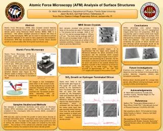
Introduction to Atomic Force Microscopy. AFM Background. Invented by Binnig, Quate, and Gerber in 1986 Measures the interaction forces between the tip and surface (e.g. repulsive and attractive forces). Vertical resolution: 0.1 nm Lateral resolution: 2-10 nm


Introduction to Atomic Force Microscopy
E N D
Presentation Transcript
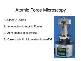
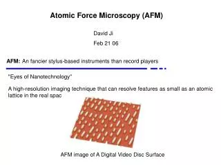
AFM Background • Invented by Binnig, Quate, and Gerber in 1986 • Measures the interaction forces between the tip and surface (e.g. repulsive and attractive forces). • Vertical resolution: 0.1 nm • Lateral resolution: 2-10 nm • Most common modes of AFM: Contact and tapping mode • Topography and other important information about the surface can be constructed into an image • Forces are measured in AFM and obey Hooke’s Law: F = k z (k = cantilever spring constant; z = vertical deflection)
z Basic Operating Principle of AFM
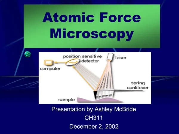
Basic Operating Principle of AFM photodiode detector The beam from a diode laser is deflected off the back of an AFM cantilever to a quadrant photodetector. As the AFM tip is raster scanned across the surface, the up-down and left-right movement of the tip is monitored by the detector and converted into images of topography and friction, respectively. diode laser laser light tip piezoceramic tube scanner sample 4
SEM micrographs of: • a square-pyramidal PECVD Si3N4tip • a square pyramidal etched single crystal silicon tip • (c) a three-sided pyramidal natural diamond tip
tip-sample separation distance Force Distance-Curves in AFM Stage (i): The tip is far away from the surface and there is no interaction between tip and the surface. No cantilever deflection occurs during stage i. Stage (ii): As the tip approaches the surface, the tip senses attractive forces causing the tip to “snap into contact” with the surface. Stage (iii): As the tip keeps approaching the surface, long and short-range repulsive forces make the cantilever deflect. Stage (iv): When the tip keeps approaching the surface, the cantilever bends resulting in a straight line appeared in cantilever deflection axis. ***As deflection reaches to maximum, the tip stops approaching and retracts from the surface.*** Stage (v): The retracting line appears because of the adhesive forces between the tip and the surface. ***Once the tip-surface separation is large enough to overcome long-range attractive interaction, the cantilever returns to zero deflection.*** Solid line: tip approaching surface Dashed line: tip retracting from surface
Contact Mode AFM • Tip remains in contact with the surface during scanning • Operates in the repulsive regime of the force curve • Tip is maintained at a constant force by moving the cantilever up and down as it scans • Topography and friction (i.e. lateral force) images are acquired simultaneously during scanning • Disadvantages: There exists large lateral forces on the sample as the tip is “dragged” over the surface. Problems with contact mode are caused by excessive forces applied by the probe to the sample. Thus, possibility of damaging delicate samples.
Tapping Mode AFM • Also called “intermittent contact mode AFM” • Tip oscillates near its resonance frequency over the sample during scanning (gently “taps” the surface). • Lateral forces are dramatically reduced and is therefore useful for working with delicate or poorly immobilized specimens on the surface. • Topography (height) and phase (elastic properties) data are acquired simultaneously during scanning. • Phase imaging: measures the difference between the phase of the driving signal and the phase of output signal detected by the photodiode detector.
Structures of Alkanethiol and Alkylsilane Self-assembled Monolayers (SAMs) Alkanethiol SAM Organosilane SAM
docosanethiol (23 Å) CH3(CH2)21SH octadecanethiol (19 Å) CH3(CH2)17SH θ = 30o decanethiol (12 Å) CH3(CH2)9SH hexanethiol (8 Å) CH3(CH2)5SH Au(111) Structures of Alkanethiol SAMs on Au(111)
Topography image Cursor profile Nanoshaving Using AFM Nanoshaved patterns produced within an octadecanethiol (ODT) SAM -The topographic image displays twelve dark squares written into an ODT matrix in ethanol. -The dark squares correspond to uncovered areas of Au(111). The areas of brighter contrast indicate taller features whereas the dark areas are shallower.
force Nanolithography Techniques: Nanografting Acc. Chem. Res. 2000, 33, 457. (S. Xu, G.-Y. Liu) • Depending on the choice of molecules, nanografting can generate patterns that are taller or shorter then the SAM matrix
Nanografting (cont’d) (A) Cross-shaped pattern of 11-mercaptoundecanol (MUD) written into matrix of ODT. (B) The simultaneously acquired frictional force image exhibits dark contrast for the MUD areas of the cross, which are terminated with hydroxyl groups. The surrounding methyl-terminated matrix areas of ODT exhibit lighter frictional contrast, clearly distinguishing the differences in surface chemistry after nanografting. (C) The line profile indicates the nanostructure is 0.7 ± 0.3 nm shorter than the matrix SAM, in close agreement with the theoretical differences in thickness (ODT = 2.1 nm, MUD = 1.5 nm).
Nanolithography Techniques: Biased-induced Lithography Chem. Rev. 2003, 103, 4367. (C. Gorman) Adv. Mater.1999, 11, 55. (R. Maoz, S. R. Cohen, J. Sagiv) • Oxidation or replacement of surface molecules • When a elevated bias voltage is applied, an electric field is generated between a conductive tip and a conductive/semi-conductive sample • Surface molecules beneath the tip will become oxidized or replaced. • Operating conditions: • - Performed in air • - Tip is in direct contact with the sample during scanning
Nanolithography Techniques: Dip-Pen Lithography Science1999, 283, 661. (C. Mirkin) • The AFM tip (pen) is coated with the molecules to be written (ink), and a clean substrate serves as the paper. • The molecular ink must have an affinity for both the AFM tip and for the substrate. For example, n-alkanethiols attach to silicon nitride AFM tips through physisorption (physical adsorption) and bind to surfaces of certain metals through chemisorption. • Molecules are transported to the surface via capillary diffusion through the nanoscopic water meniscus formed between the tip and sample in an ambient environment. • The transfer of the ink is dependent on the relative humidity, which affects the size of the water meniscus formed between the tip and the surface. • Tip is held in contact with the surface for certain time intervals.
Dip-Pen Lithography (cont’d) Octadecanethiol and mercaptohexadecanoic acid nanopatterns written with DPN
An “approach curve” or “force-distance” curve displays the vertical cantilever bending vs. lever-sample displacement. This displacement is measured between the sample and the rigidly held rear end of the cantilever (as opposed to the front end with the tip which will bend in response to interaction forces). (i) The lever and sample are initially far apart and no forces act. (ii) As the lever is brought close to the sample, the tip senses attractive forces which cause the end of the lever to bend downward, thus signifying a negative (attractive) force. (iii) The attractive force gradient exceeds the spring constant of the lever at this point, and this instability causes the tip to snap into contact with the sample. (iv) The lever-sample displacement can continue to be reduced. Since this tip is in repulsive contact with the sample, the front end of the lever is pushed further and further upward. The force corresponds to the externally applied load. (v) The motion is reversed. Adhesion between the tip and sample maintains the contact although there is now a negative (tensile) load. (vi) Finally the tensile load overcomes the adhesion or pull-off force and the tip snaps out of contact with the sample.