Understanding Insulator Properties in High Voltage Engineering
Learn how to calculate dissipation factor, dielectric losses, and capacitive reactive power of insulators with parallel capacitors. Explore the effects of different insulation materials and field strengths on voltage distribution.


Understanding Insulator Properties in High Voltage Engineering
E N D
Presentation Transcript
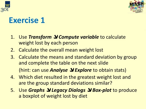
Exercise 1 S-18.3150 High Voltage Engineering S-18.3146 Suurjännitetekniikka
Question 1: • An insulator is composed of two parallel connected plane capacitors C1 = 100 nF and C2 = 200 nF with loss angles (dissipation angles) = 4.6º and = 5.7º. Electrode distance is 3mm. VRMS is 6 kV at 50 Hz. • What is the insulator’s dissipation factor (loss tangent)? • Calculated the insulators dielectric losses and capacitive reactive power Q.
Capacitance: jB Y Susceptance: Gi Ci Conductance: δ G Dissipation Factor: Admittance Y: Apparent Power: Dielectric Losses: Capacitive Reactive Power:
Question 2: • A capacitor’s electrodes are coated with insulation sheets with permittivity ε1 and ε2 and respective electric field strength E1 and E2. The electric field for the air between the electrodes is E0. Both plates have an area of 0.2 dm2 and voltage between the plates is 100V. What are the insulator’s relative permittivity values and electric field strength of each layer when E1 : E0 : E2 = 2 : 8 : 3. U = 100 V E1 E0 E2 A = 0.2 dm2 ɛ0 ɛ1 ɛ2 1 mm 1 mm 1 mm
1 2 ε1 ε2 D1 D2 The normalcomponent of electricfluxdensityD = ɛE is constant at the materialboudnaries (D1n = D2n) Removeɛ0: and Voltageoverelectrodes:
30 mm 60 mm 100 mm Question 3: • The conductor of a bushing has a diameter of 30 mm. The conductor is surrounded by 15 mm thick hard board shell with relative permittivity of 4.5. The shell is enclosed in an oil container with 100 mm diameter. Relative permittivity of oil is 2.2. • How many percent does the field strength on the surface of the metal conductor decrease due to the hard board shell? • How is applied voltage distributed amongst the insulation layers when U = 50 kV.
εr2 εr1 r3 r2 U2 U1 r1 U Without hard board (no ɛr1): • With hard board (including ɛr1): Decrease in electricfielddue to hardboardlayer:
εr2 εr1 r3 r2 U2 U1 r1 U Voltagedistribution in the layers, U = 50 kV: Frompreviousslide: U1 U InsertQ into U1