Download
1 / 24
240 likes | 474 Vues
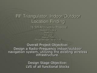
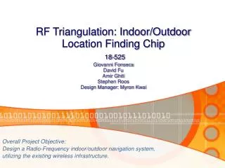
RF Triangulation: Indoor/Outdoor Location Finding Chip 18-525 Giovanni Fonseca David Fu Amir Ghiti Stephen Roos Design Manager: Myron Kwai. Overall Project Objective: Design a Radio-Frequency indoor/outdoor navigation system, utilizing the existing wireless infrastructure.

E N D
RF Triangulation: Indoor/Outdoor Location Finding Chip18-525 Giovanni FonsecaDavid FuAmir GhitiStephen RoosDesign Manager: Myron Kwai Overall Project Objective: Design a Radio-Frequency indoor/outdoor navigation system, utilizing the existing wireless infrastructure.
Project Description 65.7K • Use existing 802.11 wireless signals to calculate one’s location when GPS is not available. • The RF Triangulator will use existing infrastructure to act as an indoor/outdoor local positioning system • Using distances calculated from signal to noise ratios from 3 or more wireless access points it will be possible to determine one’s coordinates to within 1 meter.
Motivation & System Integration • It will be able to quickly provide your current location and aid in path finding. • Can be used by outdoor venues such as amusement parks, tourist areas or college campuses to provide interesting information. • To be used indoors to privately locate resources or navigate unfamiliar buildings • Our chip can be integrated into handheld computers, watches, cell phones or shopping carts for locations ranging from large theme parks to office buildings. 65.7K
Our Vision 65.7K
Triangulation Algorithm • Our chip will solve for the simultaneous solution of 3 circle equations – done by the Calc module http://geology.csupomona.edu/drjessey/class/Gsc101/triangulation.gif 65.7K
Calculations for Calc 65.7K
Other Components 65.7K • Top Three: Tracks and ID’s best (closest) three signals utilizing distance and access point MAC address. Calculates moving average of signal distance to reduce noise. Caches four recently seen signals. • SRAM: Can be loaded with local access point locations and updated as you move.
Dataflow 65.7K
Design Process • Split design into 4 pieces: lookup table, top three, calc and the fpu modules • Original specifications for the chip included 16-bit floating point calculations and a waypoint finder utilizing a trig lookup in RAM that could show the direction to your desired location. • Size and complexity constraints reduced floating point numbers to 12-bits and eliminated waypoint calculation • 1KB SRAM = 48,000+ transistors =>1800bit SRAM • Reduced transistors by receiving distance as an input instead of calculating it. 65.7K
Floorplan Evolution 65.7K
Floorplan Evolution Top3 lookup CALC 65.7K
Floorplan Evolution 65.7K Top3 CALC lookup
Floorplan Evolution 65.7K Top3 CALC lookup
Floorplan Evolution Top3 CALC lookup 65.7K
Lookup Verification 22: r=1, w=0, rst=1, mI=000000000000, xin= 9, yin= 9, mO=xxxxxxxxxxxx, x= x, y= x, f=0, d=0, o=0, clk=0 23: r=1, w=0, rst=1, mI=000000000000, xin= 9, yin= 9, mO=000000000000, x= 0, y= 0, f=1, d=1, o=0, clk=1 24: r=0, w=0, rst=1, mI=000000000000, xin= 9, yin= 9, mO=000000000000, x= 0, y= 0, f=1, d=1, o=0, clk=0 25: r=0, w=0, rst=1, mI=000000000000, xin= 9, yin= 9, mO=000000000000, x= 0, y= 0, f=0, d=1, o=0, clk=1 26: r=1, w=0, rst=1, mI=000000000005, xin= 9, yin= 9, mO=000000000000, x= 0, y= 0, f=0, d=1, o=0, clk=0 27: r=1, w=0, rst=1, mI=000000000005, xin= 9, yin= 9, mO=000000000000, x= 0, y= 0, f=0, d=0, o=0, clk=1 28: r=1, w=0, rst=1, mI=000000000005, xin= 9, yin= 9, mO=000000000000, x= 0, y= 0, f=0, d=0, o=0, clk=0 59: r=0, w=1, rst=1, mI=000000000009, xin= 9, yin= 9, mO=000000000009, x= 9, y= 9, f=0, d=0, o=0, clk=1 60: r=1, w=0, rst=1, mI=000000000005, xin= 9, yin= 9, mO=000000000009, x= 9, y= 9, f=0, d=0, o=0, clk=0 61: r=1, w=0, rst=1, mI=000000000005, xin= 9, yin= 9, mO=000000000005, x= 9, y= 9, f=1, d=1, o=0, clk=1 62: r=0, w=0, rst=1, mI=000000000005, xin= 9, yin= 9, mO=000000000005, x= 9, y= 9, f=1, d=1, o=0, clk=0 63: r=0, w=0, rst=1, mI=000000000005, xin= 9, yin= 9, mO=000000000005, x= 9, y= 9, f=0, d=1, o=0, clk=1 64: r=1, w=0, rst=1, mI=000000000017, xin= 9, yin= 9, mO=000000000005, x= 9, y= 9, f=0, d=1, o=0, clk=0 65: r=1, w=0, rst=1, mI=000000000017, xin= 9, yin= 9, mO=000000000005, x= 9, y= 9, f=0, d=0, o=0, clk=1 65.7K Rise Time: 78.2 ps Fall Time: 66.1ps
Top Three Verification 65.7K • *OP: UPDATE @ t = 260 • INPUTS: [ ID = 0000aaaabbbb SNRr = 80 clk|rst = (1|1) ] • LOOKUP: [ ID = 0000aaaabbbb (X,Y) = ( 20, 30) (SNRt,SNRr) = ( 200, 80) ] • NEWROW: [ ID = 0000aaaabbbb (X,Y) = ( 0, 0) (SNRt,SNRr) = ( 0, 80) ] • ROW A : [ ID = 000000000000 (X,Y) = ( 0, 0) (SNRt,SNRr) = ( 0, 0) R(1) ] • ROW B : [ ID = 0000aaaabbbb (X,Y) = ( 20, 30) (SNRt,SNRr) = ( 200, 300) R(1) ] • ROW C : [ ID = 000000000000 (X,Y) = ( 0, 0) (SNRt,SNRr) = ( 0, 0) R(0) ] • SAMPLA: [ Sample 1 = 0 Sample 2 = 0 Sample 3 = 0 Sample 4 = 0 Average = 300 ] • SAMPLB: [ Sample 1 = 300 Sample 2 = 300 Sample 3 = 300 Sample 4 = 300 Average = 300 ] • SAMPLC: [ Sample 1 = 0 Sample 2 = 0 Sample 3 = 0 Sample 4 = 0 Average = 300 ]
Calc Verification >./fpu_optest -md -single 3009 5 --Input– A: 101111000001 (3009) B: 000000000101 (5) --Results– prod: 0000 0000 0001 (1) quo: 0010 0101 1001 (601) rem: 0000 0000 0100 (4) Done 65.7K
Issues Encountered • Slow or incomplete rise times from lack of buffering especially in SRAM • Triangulation algorithm conversion to hardware was difficult • Registers became larger than expected • Underestimated bus sizes especially in top three with several 48+ bit buses 65.7K 65.7K 65.7K 65.7K 65.7K
Pin Specifications • PIN COUNT : Input – clk, Output – 12-bit X, reset, 12-bit Y write, = 24 output pins 48-bit MAC, 12-bit X, InOut – Vdd!, Gnd! 12-bit Y, 12-bit Distance = 87 input pins Total Pins = 115 65.7K
Part Specifications Top Three: 29,322 trans. • 3 x FPU Add/Sub Units: 4500 trans. • Registers: 16104 trans. • Muxes & Computation: 8718 trans • Area: 602x512 u2 • Density: .095 trans/u2 FPU Adder: 2,160 trans. • Prenorm 866 trans. • Postnorm 988 trans. • Adder 306 trans. • Area: 136x76 u2 • Density: .21 trans/u2 FPU Mult/Divide: 5,601 trans. Prenorm 1032 trans. Postnorm 1527 trans Mult/Divide 3042 Area: 180x195 u2 Density: .16 trans/u2 • Lookup: 15,018 trans. • Control Registers & Muxes: 2094 trans. • Control Logic: 163 trans. • Computation: 611 trans. • SRAM: 12,150 trans. • Area: 210x240 u2 • Density: .3 trans/u2 • Calc: 21,379 trans. • 2 x FPU Add/Sub Unit: 2160 trans. • 1 x FPU Mult/Div Unit: 5601 trans. • 1 x Shifter: 206 trans. • 1 x Comparator: 282 transistors. • FSM Logic: 1106 transistors • 25 x 12-bit Registers: 6600 trans. total • 8-1,6-1,4-1,2-1 Mux Sets: 3264 • Area: 200x720+400x200 u2 • Density: .08 trans/u2 65.7K
Chip Specifications 65.7K • Total Chip: 65,719 transistors • Area: 712x871 u2 • Density: 0.106 trans/u2 • Aspect Ratio: 1.13 • Speed: 100Mhz
Conclusion • A good floorplan is essential for a good layout • To ensure ExtractedRC results are ok buffering and simulations on schematics are key • Group communication is very important Stay within design limits