Download
1 / 40
400 likes | 558 Vues
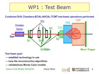
ANTI-2 Test Beam. Paolo Valente on behalf of the LAV team. Test beam objectives. Validate final version of front-end electronics plus modifications of voltage divider: Time-over-threshold vs. charge calibration curves Efficiency vs. threshold for electrons, hadrons and muons

E N D
ANTI-2 Test Beam Paolo Valente on behalf of the LAV team
Test beam objectives • Validate final version of front-end electronics plus modifications of voltage divider: • Time-over-threshold vs. charge calibration curves • Efficiency vs. threshold for electrons, hadrons and muons • Test new FEE with TELL1 readout All that on a full, final ANTI ring, and thus also checking: • construction techniques • cabling and connectors • new DB37 signal flanges • new ground feed-through on HV flange
Signal and HV flanges Read half of the channels: - 16 out of 32 channels for each of the 5 layers (5/10 DB37 connectors) HV supplied to all 160 ch’s (Luckily the gain equalization done in Frascati was fine and we had not to change the HV settings)
Readout map Side B Side A (powered, but not read-out) Channel 10 Channel 1 (17, 33, 49, 65)
Readout configurations We have used three different configurations: • Phase 1: readout by 5 FE boards as in 2009 test: • 5×16 input ch’s Threshold 5×16 out LVDS TDC • 5×16 input ch’s5×16 analog out delays QDC • Phase 2: insert prototype of final FE board: • 8 input ch’s2 Thresholds 2×8 out LVDS TDC • 8 input ch’s 2 Analogue 4-fold sum delays QDC • Phase 3: back to old FE boards • efficiency studies • final FE prototype connected to TELL1 for readout tests
Setup (1) “front” Trigger: • 2 scintillators(cross) in “front” of the ANTI-2, defining a 6×6 cm2 area (AND) • 1 scintillatoron the “back” • generally NOT used as veto, but only for checking longitudinal containment “back”
Setup (2) 2 beam Cerenkov counters (TDC & QDC): • Operated at two different pressures to have, in a given momentum range: • Cerenkov A: threshold between e and m • Cerenkov B: threshold between m and p
Setup (3) Wire chamber Trigger scintillators Beam scintillator Focus at wire chamber + 2m Beam Cerenkov
Most hit crystals map 13 29 45 61 77 12 28 44 60 76 11 27 43 59 75 10 26 42 58 74 9 25 41 57 73 8 24 40
Online counts (TDC) Layer 1 Layer 2 Layer 3 Layer 4 Layer 5 Scintillators & coincidence New front-end board (double threshold) Empty
TDC hit-map # of hits channel #
Charge vs. ToT QDC (pC) ToT (ns) Run 627, Threshold=4 mV Run 638, Threshold=8 mV
Charge vs. ToT QDC (pC) ToT (ns) Run 627, Threshold=4 mV Run 638, Threshold=8 mV Threshold not changed (broken test point)
Charge vs. ToT Run 178
An effect due to geometry?... 28 11 27 43 59 58 25 41 57
New FE board 8 channels × thresholds: Channel 10, 11 Channel 26, 27 Channel 41, 42 Channel 58 Channel 74 Analog sum 1 Analog sum 2
QDC (pC) Old FE board QDC is fed with individual channel analog signal (channel 41) Run 178 New FE board QDC is fed with 4-fold analog sum (channels 41+42+58+74) In final configuration, this will be the sum of the four crystals in one “banana” ToT (ns) Run 202
Total charge with ToT vs. QDC 0.3 GeV run 4th order polynomial parametrizationof charge vs. ToT curve Compare charge from QDC with charge from ToT
Muon selection Scintillator 2 (pC) Scintillator 2 (pC) Scintillator 1 (pC) Scintillator 1 (pC) + ask for hit crystal in previous and following layer + isolation cut (allowed only additional hit in the nearby crystal)
FE threshold Threshold = 8 mV Efficiency Make the ratio, Fit the threshold profile Charge (pC) Charge (pC) Black: all events Red: with TDC hit Profiting of the only muon runs… (Lau configuration: 8 GeV hadrons + beam stopper, fully open collimators)
Threshold calibration From known threshold, extract mVpC conversion Threshold (pC) Threshold (mV)
Muon efficiency Efficiency Muon runs Layer 5 Layer 4 Layer 3 Layer 2 Layer 1 Threshold (mV)
Muon efficiency vs. threshold Efficiency Muon runs … but a lot of work is needed in order to have a better understanding of data, Just one example: what is the effect of the mis-tagging of the scintillators trigger? Monte Carlo (K. Massri) Layer 1 data Threshold (pC)
Muon efficiency vs. threshold Efficiency Muon runs … moreover, the horizontal scale depends on the photo-electron to pC conversion factor (and thus on the exact gain) Monte Carlo (K. Massri) Layer 2 data Threshold (pC)
Considerations on efficiency studies We should consider that this will not be the way photons will hit our veto stations
Comparison with Monte Carlo Fraction of energy in veto station (E0=0.5 GeV) vs. azimuthal and polar angles (and projections) D. Di Filippo
We have tried to perform an horizontal scan (+10 cm, +20 cm towards the center of the ring) by moving our trigger scintillators, in order to check the impact of the lateral “cracks”. Since we did not move the ANTI-2, one should take into account also the angle. Analysis is ongoing…
Cerenkov counters Cerenkov 2 (pC) Cerenkov 1 (pC)
Electron selection 0.5 GeV 1 GeV Run 663 Run 656 Total Energy (pC) All Scintillators Scintillators + Cerenkov
Electron selection 3.5 GeV 2 GeV Run 548 Run 647 Total Energy (pC) All Scintillators Scintillators + Cerenkov
New FE + TELL1 test • 4 crystals on layer 1 and 4 crystals on layer 2 on opposite hemisphere with respect to beam impact point (only muon halo events) • fed to new FE board • readout by TDCB on TELL1
To do list • To do: • Data quality: • Selection of good runs, check all channels, hardware changes, etc. • Time resolution • Electron efficiency vs. energy: • In order to do this, we have to improve on the tagging of the incoming particle, e.g. we can ask for a deposit in the crystal in the first • Linearity, containment vs. impact point, etc.
Conclusions • All in all, the ANTI-2 test was positive from the point of view of: • Signal and HV flanges modifications • New FE board functionality (both for ToT discriminator and for analog sum circuit) • Basic test of FE board/TELL1 + TDC board matching • We collected a lot of useful data (still to be analyzed…): • We had runs at 0.3, 0.5, 1, 1.5, 2, 3, 4, 6, 8 GeV (with steeply decreasing fraction of electrons/muons+pions) and also dedicated purely muons runs • We have performed threshold scans and a threshold vs. energy calibration, demonstrating that in a good noise (grounding) situation we can work at a fraction of MIP (1/3 maybe even 1/4)
Useful info E-logbook Data repository
Special acknowledgements In addition to all the members of the LAV team: • Horst Brueker, PS & SPS coordinator • Lau Gatignon, for continuous support with the beam • AntoninoSergi, “special guest” of the entire test, putting his hands in almost everything • GianlucaLamanna, Bruno Angelucci, TELL1 gurus