Configurable System-on-Chip: Xilinx EDK
240 likes | 527 Vues
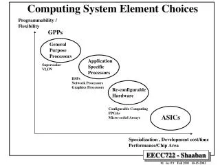
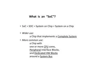
Configurable System-on-Chip: Xilinx EDK. Enno Lübbers Computer Engineering Group University of Paderborn enno.luebbers@uni-paderborn.de. EPROM. Field-Programmable Gate Arrays (FPGAs). Fine-grained reconfigurable hardware

Configurable System-on-Chip: Xilinx EDK
E N D
Presentation Transcript
Configurable System-on-Chip: Xilinx EDK Enno LübbersComputer Engineering GroupUniversity of Paderbornenno.luebbers@uni-paderborn.de
EPROM Field-Programmable Gate Arrays (FPGAs) • Fine-grained reconfigurable hardware • Gate-Array: regular structure of “logic cells”, connected through an interconnection network • Configuration stored in SRAM, must be loaded on startup FPGAs FPGA Tool Flow System on Chip (SoC) SoC Tool Flow Demonstration
HDL(VHDL /Verilog) Synthesize Netlist Map Place Route Bitstream FPGA toolflow • Hardware design is traditionally done by modeling the system in a hardware description language • An FPGA “compiler” (synthesis tool) generates a netlist, • which is then mapped to the FPGA technology, • the inferred components are placed on the chip, • and the connecting signals are routed through the interconnection network. FPGAsFPGA Tool Flow System on Chip (SoC) SoC Tool Flow Demonstration
Register a D Q output b clk clear reset HDL Synthesis HDL(VHDL /Verilog) process(clk, reset) begin if reset = ‚1‘ then output <= ‚0‘; elsif rising_edge(clk) then output <= a XOR b; end if; end process; Synthesize Netlist Map Place Route Bitstream FPGAsFPGA Tool Flow System on Chip (SoC) SoC Tool Flow Demonstration
Register a D Q output b clk clear reset Technology Mapping HDL(VHDL /Verilog) Synthesize Netlist Map Place Route Bitstream FPGAsFPGA Tool Flow System on Chip (SoC) SoC Tool Flow Demonstration
Place & Route HDL(VHDL /Verilog) Synthesize Netlist Map Place Route Bitstream FPGAsFPGA Tool Flow System on Chip (SoC) SoC Tool Flow Demonstration
Xilinx ISE FPGAsFPGA Tool Flow System on Chip (SoC) SoC Tool Flow Demonstration
Power Supply CLK EthernetMAC CLK AudioCodec InterruptController Timer GP I/O AddressDecodeUnit CPU(uP / DSP) UART Co-Proc. LC Memory Controller customIF-logic CLK SRAM SRAM SRAM DisplayController SDRAM SDRAM Traditional Embedded System Images by H.Walder FPGAs FPGA Tool Flow System on Chip (SoC) SoC Tool Flow Demonstration
Power Supply CLK CLK AudioCodec FPGA LC SRAM SRAM SRAM SDRAM SDRAM Traditional Embedded System EthernetMAC InterruptController Timer GP I/O AddressDecodeUnit CPU(uP / DSP) UART Co-Proc. Memory Controller customIF-logic CLK DisplayController Images by H.Walder FPGAs FPGA Tool Flow System on Chip (SoC) SoC Tool Flow Demonstration
AudioCodec EPROM Power Supply LC SRAM SRAM SRAM SDRAM SDRAM Configurable System on Chip (CSoC) Images by H.Walder FPGAs FPGA Tool Flow System on Chip (SoC) SoC Tool Flow Demonstration
Advantages • Fewer physical components • Shorter development cycles • Field-programmable (updates, new features...) • Possibly higher performance through on-chip integration • Signals on a chip can typically be clocked higher than signals across board traces • Optimization between modules possible • Partial reconfigurability • Exchange peripherals while the rest of the system keeps running FPGAs FPGA Tool Flow System on Chip (SoC) SoC Tool Flow Demonstration
Embedded CPUs • PowerPC 405 (hard core) • 32 bit embedded PowerPC RISC architecture • Up to 450 MHz • 2x 16 kB instruction and data caches • Memory management unit (MMU) • Hardware multiply and divide • Coprocessor interface (APU) • Embedded in Virtex-II Pro and Virtex-4 • PLB and OCM bus interfaces • MicroBlaze (soft core) • 32 bit RISC architecture • 2-64 kB instruction and data caches • Barrel Shifter • Hardware multiply and divide • OPB and LMB bus interfaces • Others • NIOS (Altera), ARM, PicoBlaze (Xilinx), ... Images by Xilinx FPGAs FPGA Tool Flow System on Chip (SoC) SoC Tool Flow Demonstration
CoreConnect Bus Architecture • Flexible bus architecture for embedded Systems and SoCs • Developed by IBM • Used by Xilinx EDK • Processor Local Bus (PLB) • On-Chip Peripheral Bus (OPB) • Device Control Register Bus (DCR) • Alternatives: • AMBA (Altera) • Wishbone (OpenCores) • Proprietary bus architectures FPGAs FPGA Tool Flow System on Chip (SoC) SoC Tool Flow Demonstration
Bus Configurations Images by H.Walder LMB: Local Memory Bus (for on-chip memory) OPB: On-Chip Peripheral Bus FPGAs FPGA Tool Flow System on Chip (SoC) SoC Tool Flow Demonstration
HDL(VHDL /Verilog) Platform Description Synthesize Netlist Generation Netlist Netlist VHDL Map Xilinx ISE (VHDL Edit, Map, Place & Route) XST (Map, Place & Route) Place Route Bitstream Bitstream CSoC Design Flow (Hardware) • Platform description is translated/assembled into netlist, which in turn is either • mapped, placed and routed onto FPGA, or • imported into ISE and used in a larger FPGA design FPGAs FPGA Tool Flow System on Chip (SoC) SoC Tool Flow Demonstration
Platform Description Netlist Generation Netlist VHDL Xilinx ISE (VHDL Edit, Map, Place & Route) XST (Map, Place & Route) Bitstream CSoC Design Flow (Hardware) FPGAs FPGA Tool Flow System on Chip (SoC) SoC Tool Flow Demonstration
*.a Platform Description User sources Library Generation *.h *.c *.h Netlist Generation Netlist Update Bitstream *.elf XST or ISE (Map, Place & Route) Bitstream with executable Code Program Bitstream CSoC Design Flow (Software) Compile & Link FPGAs FPGA Tool Flow System on Chip (SoC) SoC Tool Flow Demonstration
*.a Platform Description User sources Library Generation *.h *.c *.h Netlist Generation Netlist Update Bitstream *.elf XST or ISE (Map, Place & Route) Bitstream with executable Code Program Bitstream CSoC Design Flow (Software) Compile & Link FPGAs FPGA Tool Flow System on Chip (SoC) SoC Tool Flow Demonstration
MicroBlaze CPU Core DOPB GP I/O ILMB DLMB BRAM Demonstration • Simple System: LED Counter • Bus Configuration: • MicroBlaze CPU • Instruction- and data memoriesattached to local memory buses • General Purpose I/O (GPIO)attached to data-side OPB • Target: Xilinx Spartan-III (XC3S200) • 200’000 gates (4’320 logic cells) • 480 CLBs (24 x 20) • 216 Kbits Block RAM • 173 User I/O pins • 12 18x18 bit multipliers Image by H.Walder FPGAs FPGA Tool Flow System on Chip (SoC) SoC Tool Flow Demonstration
E14 CLK LED0 RST F13 G13 N16 N15 R16 LED7 P16 P15 Demonstration Spartan III FPGA 50 MHz clock(back side) 7-segment display Reset button Image by H.Walder FPGAs FPGA Tool Flow System on Chip (SoC) SoC Tool Flow Demonstration
Questions? • More information on Xilinx FPGAs and design tools • http://www.xilinx.com • http://www.xilinx.com/edk • Student projects / Thesises (DA/SA/BA/MA) • Enno LübbersP1.7.08.4enno.luebbers@upb.de FPGAs FPGA Tool Flow System on Chip (SoC) SoC Tool Flow Demonstration