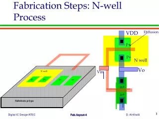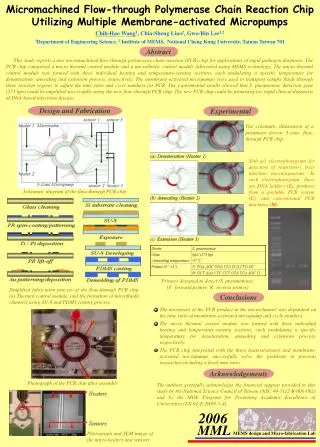
Micro-fabrication Process
Micro-fabrication Process. Clean Room. Clean room classifications and applications. Clear room classification. Class 1000: fewer than 1,000 particles (>0.5μm) in 1 cubic foot of air Class 100: fewer than 1,00 particles (>0.5μm) in 1 cubic foot of air. Micromachining Materials.

Micro-fabrication Process
E N D
Presentation Transcript
Clear room classification • Class 1000: fewer than 1,000 particles (>0.5μm) in 1 cubic foot of air • Class 100: fewer than 1,00 particles (>0.5μm) in 1 cubic foot of air
Micromachining Materials • Substrates: • Silicon • GaAs • Other elemental or compound semiconductors • Metals (bulk and foils) • Glasses • Quartz • Sapphire • Ceramics • Plastics, polymers and other organics
Micromachining Materials • Additive Materials: • Silicon (amorphous, polycrystalline, epitaxial) • Silicon compounds (oxides, nitrides, carbides, …) • Metals and metal compounds • Glass • Ceramics • Polymers and other organics • Biomaterials
Cubic Lattices • Simplest arrangements of atoms in three dimension in which the unit cell is a cubic volume • Simple Cubic (sc) structure has an atom located at each corner of the unit cell • Body Centered Cubic (bcc) has an additional atom at the center of the cube • Face Centered Cubic (fcc)unit cell has atoms at the eight corners and on the six faces.
sc bcc fcc Cubic Lattices a is lattice constant • How is the arrangement of atoms in Silicon? • Silicon has fcc + (1/4x, 1/4y, 1/4z) fcc structure
Si crystal structure Si crystal= fcc +1/4(x,y,z)fcc
c (214) plane b a Planes and directions Lattice vector R= r*a+ s*b+ t*c, r, s & t are integers We can define a plane in a crystal lattice with three integer, called Miller indices • 1. Find the intercepts of the plane in terms of integral multiples of the basis vectors • [Fig2, 4, 1] • Take the reciprocal of the integers and reduce to smallest set of integers h, k, l, in this case 2,1,4 • Label the plan (214) & direction is <214>
Blue is (010) plane, yellow arrow is <010> dirn c c c Blue is (100) plane, yellow arrow is <100> dirn Blue is (110) plane, yellow arrow is <110> dirn b b b a a a Planes and directions
Czochralski Method • For growing single-crystalline ingot
懸浮帶區法(FZ法) • 因CZ法缺點,乃因坩鍋內的氧原子會滲入單晶錠長晶過程中。 • FZ法可以生產含氧量非常低的單晶錠。 • 先以模子鑄出含摻雜物多晶矽棒。 • 種晶被熔融並接合於棒的下端。 • 射頻(RF)加熱線圈沿軸向上移動,多晶棒熔融,原子排成種晶方向。 • 缺點 –無法生成大直徑晶錠。 –差排(dislocation)密度較高。 • 生成的晶錠以製造 –功率晶體(thyristor) 。 –大功率整流元件(rectifier) 等為主要目的。
比較柴氏和浮動區長晶法 兩法之比較 • 柴氏法(Czochralski) –較普遍、便宜。 –較大晶圓尺寸 (300 mm in production) 。 –原料可再度使用。 • 懸浮帶區法(FZ法) –純矽晶(無坩堝) 。 –較昂貴,晶圓尺寸較小(150 mm) 。 –主要用來製造分離式功率元件所需晶圓。
晶圓的備製 • 去除末端:用鋸將晶錠的兩端(頸及尾)切除。 • 研磨直徑尺寸:用無心研磨機(centerless grinder)。 • 檢測結晶方向、導電形式,以及阻抗性結晶方向檢測方法-X光繞射(diffraction)、平行(collimated)光束折射。 • 晶錠刻意偏移主方向(off-orientation)幾度:離子植入。
晶塊修整 • “裁切”錐形的晶塊與錐體末端。 • 驗證程序控制以控制小塊金屬或雜質。 晶塊本體研磨至所需直徑,並加上平的或槽口記號。
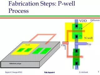
Silicon Wafer Cuts Miller indices indicated by ground edges called “flats”. “n”-type and “p”-type refer to “doping”. N means “negative” (phosphorous) and P means “positive” (boron).
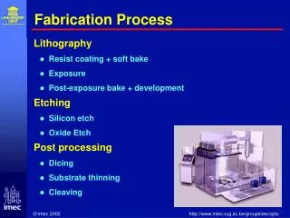
Etching Mechanism • Etching type Wet etching Dry etching • Etching steps Oxidation Reaction Remove products
Factors in Wet Etching • Limited • Reaction limited • Diffusion limited • Factors • Concentration • Temperature • Stirring
HNA system Anisotropic Wetting Etching