Principles of RPD Design
770 likes | 8.33k Vues
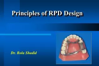
Principles of RPD Design. Dr. Rola Shadid. Differentiation between tooth-supported and tooth-tissue supported partial denture . 1. The manner in which each is supported 2. The method of impression registration and jaw record required for each 3. The need for some kind of indirect retention

Principles of RPD Design
E N D
Presentation Transcript
Principles of RPD Design Dr. RolaShadid
Differentiation between tooth-supported and tooth-tissue supported partial denture 1. The manner in which each is supported 2. The method of impression registration and jaw record required for each 3. The need for some kind of indirect retention 4. The denture base material 5. Differences in Clasp Design
Distortion of tissues over edentulous ridge will be approximately 500 microm under 4 newtons of force, whereas abutment teeth will demonstrate approximately 20 micromof intrusion under the same load.
Components of Partial Denture Design • Tooth support & ridge support • Major & minor connectors • Direct retainers • Stabilizing components • Guiding planes • Indirect retainers
Guiding Plane • the body of an extracoronal direct retainer, • the stabilizing arm of a direct retainer • the minor connector portion of an indirect retainer • or by a minor connector specifically designed to contact the guiding plane surface.
Direct Retainer Selection Class I & II (Tooth & Tissue-Borne) • Stress releasing direct retainers Class III & IV (Tooth-Borne) • Non-stress releasing direct retainers
Rest Placement: Tooth-Borne RPD’s Adjacent Edentulous Space • Most effective placement of support • Ease of preparation • Reduces minor connectors • Very rare exceptions
Retainer Selection: Tooth-Borne RPD’s • Minimal rotation • Stress release usually unnecessary • Choose non-stress releasing retainers: • Cast Circumferential * • Ring Clasp • Embrasure Clasp (Double Akers) • Reverse Action (‘C’) Clasp
Tooth-Borne Direct Retainers • Cast suprabulge clasps • Exceptions • Use stress-releasing clasps when: • Esthetics • use infrabulge or w.w. • Poor prognosis for posterior abutment
2 strategies are adopted to either 1. change the fulcrum location and subsequently the "resistance arm" engaging effect (mesial rest concept) 2. use of flexible arm (wrought-wire retentive arm). Stress-Releasing Direct Retainers
Stress-Releasing Direct Retainers Mesial Rest Concept • Rotation: retentive tip, proximal plate • Move mostly down (and forward) • Into more undercut (release of tooth)
Non-Stress-Releasing Direct Retainers Distal Rest • Rotation: retentive tip, proximal plate • Move mostly forward (tip rotates up) • Toward height of contour (activate or bind)
Long Guiding Planes Binding, torque Not advisable Short Guiding Planes proximal plate moves into space, escape of rest Acceptable, if mesial rest not possible Distal Rest Concept
Retainer Selection:Tooth-Tissue Borne RPD’s Stress-releasing Clasps • RPI Clasp * • RPA Clasp • Combination Clasp
RPI Clasp • "R" Rest (always mesial) • "P" Proximal Plate (distal) • "I" I - Bar (buccal) *
"R" Rest (always mesial) "P" Proximal Plate (distal) "A" Aker's retentive arm (always wrought wire) RPA Clasp
Wrought-wire retentive clasp arm & cast reciprocal clasp arm Bracing and retentive arms originate from distal rest Guiding plane must not run entire occluso-gingival height Combination Clasp
C E D
Other Alterations of Axial Contours • Lowering Heights of Contour • In order not to interfere with opposing occlusion • Not to increase occlusal table • Improve esthetics • Decrease tipping forces
Lowering Heights of Contour Post Is More Readily Removed by Application of Force Near Its Top Than by Applying Same Force Nearer Ground Level
Other Alterations of Axial Contours • Raising Heights of Contour • Insufficient retention in gingival 1/3 (at least 1mm from gingiva) • Prepare undercut • Add resin above to create undercut
Preparing Retention • Axial surface must be close to parallel the path of insertion
Retentive Preparation Shape • Follows the path of designed retentive tip
Creating Undercuts with Bonded Resins • Axial surface must be close to parallel the path of insertion
Summary of Abutment Modifications • After RPD Designed • Guideplanes • Lower heights of contour to eliminate interferences & improve esthetics • Create undercuts if absolutely necessary (raising heights of contour) • Rest seat preparation
McCracken’s Removable Prosthodontics, 11th Edition 2005 by McGivney GP, Carr AB. Chapter 10 • Dalhousie continual education