Download

1 / 129
1.29k likes | 1.52k Vues
SL1000 High-Speed Data Acquisition System. SL1000 Product Training Yokogawa Corporation of America. SL1000 High Speed Data Acquisition Product Training. Objective. System Overview Main Unit Front Panel Layout Rear Panel Layout

E N D
SL1000High-Speed Data Acquisition System SL1000 Product Training Yokogawa Corporation of America
Objective • System Overview • Main Unit • Front Panel Layout • Rear Panel Layout • High-Voltage 100KS/s, 16-bit Isolation Module (with RMS) (701260) • Additional Module Library Available • Software Installation: Installing SL1000 Acquisition Software (includes File Utility Software) and Xviewer • Hardware Preparations: • Installation of modules • Setting SL1000 Group & Unit numbers • Single Unit • Multiple Units • Install of Synchronic Cable (for Multi-unit synchronization)
Objective • Single Unit Connectivity Method • USB • Connect unit to PC via USB cable • Install USB drivers • Ethernet • Caution Setting IP Address • Configure IP address using 7.A • Disconnect USB Cable • Re-connect via Ethernet Cable • Multiple Units Connectivity Method • USB • Set Group & Unit Numbers (refer section 6.B.II) • Link Units w/ Sync Cable (refer section 6.C) • Connect Units to PC via USB cable • Install USB drivers (refer section 7.A.II) • Launch SL1000 Acquisition Software • Ethernet • Configure IP Addresses (refer section7.A and 7.B) • Set Group & Unit Numbers (refer section 6.B.II) • Link Units w/ Sync Cable (refer section 6.C) • Connect Units to PC via Ethernet HUB/Router • Launch SL1000 Acquisition Software
Objective • SL1000 Acquisition Software • Overview • Connection & Group Settings • Connection Method & Unit/Channel Auto Detection • Measurement Groups • Measurement Settings • Measurement Mode & Time Settings • Sample Rate Settings • Channel Settings • Scaling Options • Trigger Settings • Alarm Settings • Recording Settings • Data Storage Destination • Start & Stop Condition • File Properties
Objective • Display settings • Assign Channels to Display Groups • Setting Display Time (for Free-run Mode only) • Other Display Settings • Graph Settings • Making Measurement • Main Display Overview • Overview of Toolbar Icons • Waveform Display Overview • Status Information Window • Saving Software Settings • Waveform Parameters (Triggered Mode Only) • Data “File Transfer” Utility • Accessing Data Transfer Utility • Overview of Data Transfer Utility • Download Data from SL1000 Hard Drive • Other Items & Cautions
Objective • File Utility Software • Accessing File Utility Software • File Conversion Function (convert to CSV) • File Merge Function (combining files from multiple units) • Example of File Merge • Waveform Acceleration Function (for faster viewing in Xviewer) • Xviewer Software • Accessing Xviewer • Overview • Main Controls • Loading Saved Waveform • Loading Saved Waveform with More Options • Zoom, Cursors, Waveform Parameters & MATH • Saving Data to CSV • Saving Data between Cursors
Objective • Calibration & Service • Recommendations • Service Manual Reference • Other Recommendations • Trouble Shooting Recommendations • Checking Ethernet Connectivity • Checking Multi-unit Synchronization Mode • Verifying SL1000 Software & Firmware • Checking SL1000 Hard Drive Disk Space • Trouble Shooting Bad Channel • Error Messages (LCD Display on Main Unit) • Appendix • App 1 - Manuals & References • App 2 - Measurement Times: Free Run Mode • App 3 - Measurement Times: Single Triggered Mode • App 4 - Measurement Times: Single (N) Triggered Mode
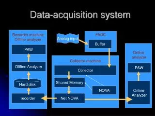
【Observation】 【Analysis】 【Measurement】 1. System Overview SL1000 Acquisition Software Xviewer (off-line analysis tool) Ethernet/USB • Control main unit • Display captured waveform/data • Record to PC HDD • Analyze data • Convert to CSV if needed Disconnect acquisition software Ethernet/USB Plug-in module Xviewer • Plug in modules (Note: modules are not hot swappable) • Connect to PC via Ethernet/USB for configuration • Keep connected to PC if recording data to PC HDD • For stand-alone operation, you do not need PC connected. Only need PC for configuration • For stand-alone operation • Download data from main unit • Analyze data using Xviewer • Convert to CSV if needed • Delete data in main unit
Digital Display (Group #, Unit #, Modules, IP Address, Error Messages, Sync Indicator, Storage Indicator) Power Indicator Trigger Indicator Start/Stop Button Display Toggle Button USB Communication Port (Rev 2.0) Probe Compensation Signal Output (1 kHz/1Vp-p) EXT CLK Input (TTL; 0 to 5V) Probe Power/Ground Input Modules 2.A. Main Unit: Front Panel Layout
2.B. Main Unit: Rear Panel Layout Trigger Output Terminal (CMOS Level; 0 to 5V) External Trigger Input Terminal (TTL; 0 to 5V) Unit Model Description Plate (720120-D/HD1/C10/P4/XV1) Ethernet Communication Port (1000 Base-T/100 Base-TX) Main Power Switch Power Supply Input (100-120V/220-240V) Rotary Switch to set Group ID & Unit ID Alarm & Remote Output Terminals GO/NO-GO Output Terminals DIP Switches (Not Used) Sync Out (To Slave Unit) Sync In (From Master Unit)
4. Additional Module Library (Existing DL750/DL750P Modules)
4. Additional Module Library (Existing DL750/DL750P Modules) ModelSpecification 701250 : High-speed 10MS/s 12 bit isolation module (2CH) 701251 : High-speed 1Ms/s 16 bit isolation module (2CH) 701255 : High-speed10MS/s 12 bit non-isolated module (2CH) 701260 : High-speed 100kS/s 16 bit isolated module (2CH) 701261 : Universal module (2CH) 701262 : Universal module (with AAF) (2CH) 701265 : Temperature/high precision voltage module (2CH) 701270 : Strain module (NDIS) (2CH) 701271 : Strain module (DSUB, shunt Cal) (2CH) 701275 : Acceleration/voltage module (with AAF) (2CH) 701280 : Frequency module (2CH) (701250/701255 may require factory work depending on shipping period)
5. Software Installation • Install the following software on the PC that is used to configure & control the SL1000: • Once the software installation is complete, you should see the following icons on your desktop: • SL1000 Acquisition Software & File Utility Software • Xviewer (off-line data analysis software)
6.A. Hardware Preparations – Installing Modules • Please note that the modules are not hot swappable. Be sure to power the unit OFF, before installing or un-installing any input modules. Fasten the screws on the module to the main frame, to make sure that the modules are firmly installed Turn main power to the device OFF and then install/uninstall modules
6.B. Setting SL1000 Group & Unit Numbers • 6.B.I Single Unit • Use the blue rotary switch on the rear panel of the device to select the Group # and Unit # Group = 0 Unit = 0 • 6.B.II Multiple Units Master Slave 2 Slave 1 Group = 0 Unit = 2 Group = 0 Unit = 0 Group = 0 Unit = 1 Power device OFF when making these settings
6.C. Installing Synchronic Cable (for Multi-unit synchronization) • With power to the device OFF, connect the SYNC Cables (part # 720901-01 OR 720901-02) as shown below for multi-unit synchronization Group = 0 Unit = 2 Group = 0 Unit = 0 Group = 0 Unit = 1 Master Slave 2 Slave 1 Slave Unit 1 Sync Out to Slave Unit 2 Sync In Master Unit Sync Out to Slave Unit 1 Sync In Power device OFF when making these connections
7.A.I. USB – Connect unit to PC via USB Cable • USB Connectivity • Make sure that the SL1000’s Group and Unit number is set to 0 • Turn ON the power the SL1000 • Connect SL1000 to PC via the Standard USB 2.0 Cable • When the SL1000 is connected to the PC for the first time, the PC will launch the installation wizard “Found New Hardware Wizard”. PC PC side Instrument side USB 2.0 Cable
7.A.II USB - Install USB Drivers • Installing USB Drivers • Please refer to document “IMB9852UT-01E_020.pdf” for instructions to complete the installation of the SL1000 USB drivers • For Windows XP users please refer to “Installing the Driver (Windows XP)” section • Complete the USB Driver installation. • If you intend to use the SL1000 via USB, then proceed to the SL1000 Acquisition Software section to establish connectivity and configure the device as needed.
7.A.II USB - Install USB Drivers (cont..) • Launch the SL1000 Acquisition Software and connect to the device via USB • Select “USB” connection method and click “Search” • Once the unit is detected under “Detected Units”, you have successfully configured the device for Single Unit USB Connectivity Click “Search” Select “USB”
7.B.I Ethernet - Caution Setting IP Address • Please make sure that the IP address of the Unit and the PC are set as follows: • If the IP address of the PC is “10.192.1.4” and Subnet Mask is “255.255.255.0” • Then make sure that the SL1000’s Ethernet settings are as follows: • IP = “10.192.1.1” • Subnet Mask = “255.255.255.0” • It is important to make sure that the PC and the SL1000 are on the same subnet mask and the IP address should only differ in the last number • The same applies when connecting multiple units. IP = 10.192.1.4 SM = 255.255.255.0 Slave 2 Slave 1 Master Group = 0 Unit = 2 IP = 10.192.1.3 SM = 255.255.255.0 Group = 0 Unit = 1 IP = 10.192.1.2 SM = 255.255.255.0 Group = 0 Unit = 0 IP = 10.192.1.1 SM = 255.255.255.0
7.B.II Ethernet – Configure IP Address using 7.A • Ethernet Connectivity • To use the SL1000 via the Ethernet interface, please establish connectivity to the device via USB first and then follow the steps below to configure then IP address • Launch the SL1000 Acquisition Software and connect to the device via USB • Select “USB” connection method and click “Search” • Once the unit is detected under “Detected Units”, add one module to “Group1” and click “OK” USB OK
7.B.III. Ethernet – Disconnect USB Cable • Select “Communication settings” from the “Environment” menu and click “Yes” • Enter “Unit Name” to identify the unit, e.g. “FAT0” • Select “DHCP” = OFF and enter “IP” address & “Subnet Mask”. Please make sure you set the IP addresses as described in section “7.B.I” • Click “Apply” & then click “OK” and disconnect the USB cable from the SL1000. • Connect the Ethernet cable to the SL1000 • At this point cycle power to the SL1000 • Once the SL1000 hardware has completed the start-up process, go the section “Connection & Group Settings” window in the SL1000 Acquisition Software.
7.B.IV. Ethernet – Re-connect via Ethernet Cable • Re-connect via Ethernet interface • Select “Ethernet” connection method and click “Search” • If the unit is detected under “Detected Units”, you have successfully configured the unit for Ethernet connectivity. Ethernet Detected Units Ethernet HUB or Router PC Ethernet Cable Ethernet Cable
8.A.I. USB – Set Group & Unit Numbers (refer section 6.B.II) • Power device OFF when making these settings • Use the blue rotary switched on the rear of the device to set the appropriate Group and Unit number Master Slave 2 Slave 1 Group = 0 Unit = 2 Group = 0 Unit = 1 Group = 0 Unit = 0
8.A.II. USB – Link Units with Sync Cable (refer section 6.C) • Power device OFF when making these connections • Connect the units with the Synchronic Cable (720901-01 or 720901-02) Group = 0 Unit = 2 Group = 0 Unit = 1 Group = 0 Unit = 0 Make sure that the cables are firmly connected from the Master (Sync Out) to the Slaves (Sync In) Master Slave 2 Slave 1 Slave Unit 1 Sync Out to Slave Unit 2 Sync In Master Unit Sync Out to Slave Unit 1 Sync In
8.A.III. USB – Connect Units to PC via USB PC USB Cable USB Cable USB Cable Master Slave 2 Slave 1 Group = 0 Unit = 2 Group = 0 Unit = 1 Group = 0 Unit = 0
8.A.IV. USB – Install USB Drivers if needed (refer section 6.B.II) • Multiple Units USB Connectivity • Prior to powering ON the units for multiple units connectivity, make sure that the SL1000’s Groups and Unit numbers are set as described in section “6.B” • Make sure that the Synchronic Cables are connected as described in section “6.C” • Make sure all the units are connected via USB to the PC. (if you don’t have enough USB ports on the PC, please use a USB 2.0 passive HUB) • Once the above items have been configured and connected, turn ON power to the SL1000’s beginning with the Master Unit first • Turn ON the power the SL1000 • When the SL1000 is connected to the PC for the first time, the PC will launch the installation wizard “Found New Hardware Wizard”. Please follow the steps described in section “Configuring SL1000 for Single Unit Connectivity (USB)” • Launch the SL1000 Acquisition Software
8.A.V. USB – Launch SL1000 Acquisition Software • Launch the SL1000 Acquisition Software • Select “USB” connection method and click “Search” • If all your settings are correct, you will see the following screen when you perform a search for multiple units connected via USB. USB Click “Search”
8.A.V. USB – Launch SL1000 Acquisition Software (cont..) • Master Unit will be “ID1” and the subsequent Slave Units will be “ID1-{unit name}”, “ID2-{unit name}” and so on. • The CH numbers will be assigned as (Master Units) CH1, CH2, CH3…..CHX…..(Slave Units) CHX+1…. Master Unit = ID0-{unit name} Master unit begins with CH1 to CHX Slave Unit = ID1-{unit name} Slave unit begins with CHX+1
8.B.I Ethernet – Configure IP Addresses (refer to 7.A & 7.B) • Configure the IP addresses of each unit using Single Unit Connectivity Method described in section 7.A and 7.B IP = 10.192.1.4 SM = 255.255.255.0 Group = 0 Unit = 2 IP = 10.192.1.3 SM = 255.255.255.0 Group = 0 Unit = 1 IP = 10.192.1.2 SM = 255.255.255.0 Group = 0 Unit = 0 IP = 10.192.1.1 SM = 255.255.255.0
8.B.II Ethernet – Set Group & Unit Numbers (refer to 6.B.II) • Power device OFF when making these settings • Use the blue rotary switched on the rear of the device to set the appropriate Group and Unit number Master Slave 2 Slave 1 Group = 0 Unit = 2 Group = 0 Unit = 1 Group = 0 Unit = 0
8.A.III. Ethernet – Link Units w/ Sync Cable (refer section 6.C) • Power device OFF when making these connections • Connect the units with the Synchronic Cable (720901-01 or 720901-02) Group = 0 Unit = 2 Group = 0 Unit = 1 Group = 0 Unit = 0 Make sure that the cables are firmly connected from the Master (Sync Out) to the Slaves (Sync In) Master Slave 2 Slave 1 Slave Unit 1 Sync Out to Slave Unit 2 Sync In Master Unit Sync Out to Slave Unit 1 Sync In
8.B.IV. Ethernet – Connect Units to PC via Ethernet HUB/Router PC Ethernet Cable Ethernet HUB or Router Ethernet Cable Ethernet Cable Ethernet Cable Slave 1 Group = 0 Unit = 1 Master Group = 0 Unit = 0 Slave 2 Group = 0 Unit = 2 Slave Unit 1 Sync Out to Slave Unit 2 Sync In Master Unit Sync Out to Slave Unit 1 Sync In Group = 0 Unit = 1 IP = 10.192.1.2 SM = 255.255.255.0 Group = 0 Unit = 0 IP = 10.192.1.1 SM = 255.255.255.0 Group = 0 Unit = 2 IP = 10.192.1.3 SM = 255.255.255.0
8.A.IV. Ethernet – Launch SL1000 Acquisition Software • Multiple Units Ethernet Connectivity • Prior to powering ON the units for multiple units connectivity, make sure that the SL1000’s Groups and Unit numbers are set as described in section “6.B” • Make sure that the Synchronic Cables are connected as described in section “6.C” • Make sure all the units are connected via an Ethernet HUB or Router to the PC. • Once the above items have been configured and connected, turn ON power to the SL1000’s beginning with the Master Unit first and then the consecutive Slave Units. • Turn ON the power the SL1000 • Launch the SL1000 Acquisition Software
8.A.IV. Ethernet – Launch SL1000 Acquisition Software (cont..) • Launch the SL1000 Acquisition Software • Select “USB” connection method and click “Search” • If all your settings are correct, you will see the following screen when you perform a search for multiple units connected via USB. USB Click “Search”
8.A.IV. Ethernet – Launch SL1000 Acquisition Software (cont..) • Master Unit will be “ID1” and the subsequent Slave Units will be “ID1-{unit name}”, “ID2-{unit name}” and so on. • The CH numbers will be assigned as (Master Units) CH1, CH2, CH3…..CHX…..(Slave Units) CHX+1…. Master Unit = ID0-{unit name} Master unit begins with CH1 to CHX Slave Unit = ID1-{unit name} Slave unit begins with CHX+1