what
This guide aims to provide specific and practical information to support your implementation of decentralised energy systems. The guide will help you understand the right solution for different situations and help you understand which groups of people you will need for delivery.

what
E N D
Presentation Transcript
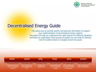
This guide aims to provide specific and practical information to support your implementation of decentralised energy systems. The guide will help you understand the right solution for different situations and help you understand which groups of people you will need for delivery. Use the buttons below to navigate around the guide. what when why how who where This section covers context for DE and the technologies involved This section covers key scenarios for the application of DE This section covers reasons to consider DE This section covers key enablers and current business models This section covers which parties you may need to deliver a DE scheme This section covers links to sources of further information
What This section provides some introductory information defining the context for decentralised energy and some of the main technologies involved. Definition of DE What you need to do first Technologies ESCo what when why how who where
Definition of Decentralised Energy There are many different definitions of “decentralised energy”. The Government takes a broad view using the term “distributed energy” to refer to the wide range of technologies that do not rely on the high-voltage electricity transmission network or the gas grid. This includes: • All plants connected to a distribution network rather than the transmission network. • Small-scale plants that supply electricity to a building, industrial site or community, potentially selling surplus electricity back into a distribution network. • Microgeneration, i.e. small installations of solar panels, wind turbines or biomass/waste burners that supply one building or small community, again potentially selling any surplus. • Combined Heat and Power (CHP) plants, including: • Large CHP plants (where the electricity output feeds into the transmission network but the heat is used locally). • Building or community level CHP plants. • ‘Micro-CHP’ plants that effectively replace domestic boilers, generating both electricity and heat for the home. • Non-gas heat sources such as biomass, wood, solar thermal panels, geothermal energy or heat pumps, where the heat is used in just one household or is piped to a number of users in a building or community. next › what when why how who where
Local Generation Distributed energy schemes use a range of fuels to generate heat and electricity more efficiently by being close to the point of use. The heat is distributed and used in district heating networks, can generate chilled water for cooling and be used in industrial processes. The electricity is sold locally or exported onto the grid. what when why how who where
Energy Efficiency Measures • Should be the starting point of any energy strategy. • Most important in achieving targets. • Insulation Technology. • Innovative solutions applied to all the micro renewable technologies. • Ongoing source of business opportunity. next › what when why how who where
Hierarchy of Energy Efficiency in Buildings Across our cities and communities these are the routes to lowering carbon emissions, reducing energy use and improving energy security, beyond central generation. what when why how who where
Energy Companies (ESCos) What is an ESCo? The precise role and responsibilities of an ESCo are tailored to meet the needs of the specific project or initiative. In general, ESCo’s are used to deliver the following objectives: • CO2 reduction; • Renewable energy projects; • Energy savings; • Energy efficiency services; • Energy advice; or • Tackling fuel poverty. However, this list is not exhaustive and one of the main benefits of an ESCo isits flexibility. ESCo’s may be used to oversee the financing, construction, operation and maintenance of the system. However the precise responsibilities of the ESCo will be tailored to meet the needs of the individual scheme. An Energy Service Company (ESCo) is not a magic wand that makes an unviable project viable, however, an ESCo may take a different view on acceptable rates of return and risk than other companies. next › what when why how who where
ESCos 2 ESCo and risk management An ESCo can spread the risk by transferring responsibility to those stakeholders best placed to manage them. In the case of financial risk, an ESCo may choose to enter into a fixed cost arrangement and incur the risk of project overspend. Not only can an ESCo reduce the risk involved in a project, it can also ensure a much more rapid outcome. By forming a group whose sole purpose is the specified project, it can provide a focussed delivery. In contrast, for example, a local authority has many responsibilities and so time management issues may result in delays to the scheme. Furthermore an ESCo can ensure that the parties managing the project have sufficient knowledge about the topic. By involving either public or private entities with previous experience implementing similar schemes, the outcome of the project can be much more secure. In some cases it can be useful to produce a risk matrix containing the risks at all stages of the project. This ensures that all eventualities have been considered, all involved parties are aware of their responsibilities, and that each stage of the project is successful. This matrix will be tailored to the specific project and include only the relevant risks. next › what when why how who where
ESCo Case Study 1 ESCo Thameswey Energy Ltd (est. 2007) Aim: Install a range of sustainable and renewable energy projects to meet the Council’s Climate Change Strategy objectives. Improve the environment within the Borough of Woking for the benefit of local residents. Mechanism: Thameswey Energy Ltd was established, a joint venture company between Thameswey Limited (a company wholly owned by Woking Borough Council) and Xergi Ltd. The ESCo was setup to finance, build and operate small scale CHP stations, to provide energy services by private wire and distributed heating networks to institutional, commercial and residential customers. Outcome: A CHP system provides heat, electricity and chilled water to district buildings. Further expansions will provide energy to other residents and revenue generated is being invested into similar schemes. next › when why how who where what
ESCo Case Study 2 ESCo 2 Aberdeen Heat & Power (est. 2000) Aim: Improve the local authority’s housing stock and reduce fuel costs for tenants. Find a more energy efficient heating method than mains electricity in the city’s multi-storey blocks. Mechanism: An ESCo was created to manage the scheme, and it in turn employed contractors and consultants to construct and install the CHP plant. Outcome: 288 flats are now connected to the community CHP scheme, which has created an annual cost saving of £83,396 for residents. The carbon savings from the scheme, compared to the existing heating systems, equate to 411 tonnes per year. next › when why how who where what
ESCo Case Study 3 ESCo 3 Southampton Geothermal Heating Company (est. 1986) Aim: That Southampton City Council “must not only advocate sustainable development, but demonstrate its commitment” by investing in energy efficient services. Mechanism: Southampton Geothermal Heating Company Ltd was created in a joint agreement between Southampton City Council and Utilicom (a specialist energy management company). The ESCo is solely owned by Utilicom so as to minimise risk for the local authority. Outcome: A geothermal well is used alongside a CHP generator to provide energy to local residents and businesses. 10,000 tonnes of carbon emissions are avoided annually and the council receive revenue of £10-15,000 a year from the sale of surplus energy. next › when why how who where what
ESCo Case Study 4 ESCo 4 Mill Energy Services Ltd (est. 2003) Aim: Meet the commitment of the developer to ensure that the refurbished apartments are carbon neutral and that carbon emissions from ground floor properties are minimised. Mechanism: An ESCo (wholly owned by the residents and tenants of the building) was created to operate and maintain the renewable energy generating assets, and to create revenue to cover ongoing costs. Outcome: A 50kW photovoltaic system and biomass CHP provide heating, electricity and drinking water to 130 apartments and several ground floor businesses. This results in approximately a 600 tonne reduction in carbon emissions annually. Various energy saving measures, including high specification windows etc, were also installed. when why how who where what
Technologies Combined Heat & Power Heat Pumps (Ground & Air) Small Scale Wind Small Scale Hydro Biomass Heating Solar Water Heating Solar Photovoltaic Combustion Gasification Fuel Cells Anaerobic Digestion Energy from Landfill Gas what when why how who where
Combined Heat & Power How it works Burns gas to produce heating and hot water. Uses internal combustion technology. Prime mover is an engine, with heat output a bi-product of electrical generation. Generation & heating equally prioritised (compared to micro CHP which is heat demand lead). Space, noise and output constraints are less of an issue (compared to domestic customers; due to plant room availability). We will ensure that your CHP is correctly sized to meet the majority of your demand for heating. It is usually more cost effective to undersize the CHP to provide the majority of your base load and use another appliance (such as a gas boiler) to provide supplementary heating. Control panel optimises electrical & heat generation. Power unit is a combustion engine. Burns fuel (nat. gas) to drive generator. Heat exchangers extract energy from exhaust and oil to provide useful heating in the premises. next › ‹ return to technologies when why how who where what
Combined Heat & Power 2 Specification Product Microgeneration Product Type Combined Heat & Power Classification Low Carbon Output 13 kW(e) 29 kW(t) Efficiency% 70% (gas) 26% (electricity) Generation 87,600 kWh(t)/yr 39,426 kWh(e)/yr Carbon Saving 75% reduction compared to Gas alone. Technology Benefits Low Carbon – Uses fossil fuels to generate heat and power in a highly efficient manner, ideal for carbon reduction and operational efficiency improvements. If fuelled by a bio fuel, then CHP can be considered a renewable or carbon neutral technology. Combined Heat & Power – The plant installed is ideal for high heating and electricity requirements. Leisure centres, schools, hospitals all fit this category. Heat requirement needs to be low temperature (<100 deg); not suitable for chemical or manufacturing processes. next › ‹ return to technologies when why how who where what
Combined Heat & Power 3 Typical Installations Schools - Good requirement for heat all year (especially with swimming pools) and high electrical demand. Hospitals - High heat and electrical demand throughout the year. Small scale heat networks – high electrical demand throughout the year. Small heat demand in summer but CHPs can be undersized with addition of efficient boilers to ensure electrical demand is sized adequately. NB addition of chiller units will improve heat demand and therefore the options are increased. ‹ return to technologies when why how who where what
Ground Source Heat Pumps How it works Solar energy stored in ground is extracted by ground loop and pumped into compressor. Compressor pressurises low temperature refrigerant to convert into high temperature thermal output for CH and DHW. Carbon & renewable credits can be earned. Government backed with grants and central funding available to offset high capital cost. Recognised in building regs and Code for Sustainable Homes. Pressure Temperature Connected Volume Solar energy is captured by ground loop water and pumped to HeatPlant. Heat transfer vaporises refrigerant in Heat Plant. Compressor compresses vapour into liquid. Low grade energy in vapour is captured as high grade heat. High grade heat is pumped around CH system. next › ‹ return to technologies when why how who where what
Ground Source Heat Pumps 2 Specification Product Microgeneration Product Type Heat Classification Renewable Output up to 40 kW(t) EfficiencyCoP 4.0 CH 3.5 DWH Generation 25,000 kWh(t)/yr Carbon Saving up to 40% compared to Gas Technology Benefits Renewable – Although GSHP uses grid supplied energy to operate; it is collecting solar energy via the ground which acts like a huge battery, storing the energy as heat. If coupled with a renewable energy tariff, or electrical generating renewables; a GSHP could be totally renewable in operation. All electric – A GSHP only requires an electrical connection to operate; ideal for off gas installations. Comparative running costs vs LPG or oil are very favourable. Grant funding applicable – Several grants, including the LCBP Phase 2 are viable for this technology. next › ‹ return to technologies when why how who where what
Ground Source Heat Pumps 3 Typical Installations Schools – Mainly new build with efficient heat circuits (underfloor or low temp rads). Village Halls – Any requirement to heat large areas with low temperatures. Offices – Any underfloor heating system or low temp circuit is ideal for improved CoP’s. next › ‹ return to technologies when why how who where what
Air Source Heat Pumps How it works Alternative to Ground Source Heat Pump installation Ambient heat from air is extracted by evaporator in compressor unit. Compressor pressurises low temperature refrigerant to convert into high temperature thermal output for CH and DHW Can work to temperatures of -20 deg. Installation is simpler than GSHP, but efficiency is less. Same technology as GSHP, only different heat source Pressure Temperature Connected Volume Energy is captured by fan unit from temperature in air. Heat transfer vaporises refrigerant in ASHP Compressor compresses vapour into liquid Low grade energy in vapour is captured as high grade heat High grade heat is pumped around CH system next › ‹ return to technologies when why how who where what
Air Source Heat Pumps 2 Specification Product Microgeneration Product Type Heat Classification Renewable Output up to 14.6 kW(t) EfficiencyCoP 3.3 CH 2.3 DHW Generation 25,000 kWh(t)/yr Carbon Saving up to 30% compared to Gas Technology Benefits Renewable – Although ASHP uses grid supplied energy to operate; it is collecting ambient energy via the air which acts like a huge battery, storing the energy as heat. If coupled with a renewable energy tariff, or electrical generating renewables; an ASHP could be totally renewable in operation. Invisible heating solution – Although efficiency isn’t as high as GSHP, the installation costs and ease of integration (no ground loops or boreholes) make ASHP an attractive proposition for retrofit applications. Typical Installations Offices – Mainly for warm air heating systems and air handling systems. (Some heat pumps can provide air conditioning but for this reason ASHP won’t attract grant funding). ‹ return to technologies when why how who where what
Biomass Heating • Burning biomass does not consume fossil fuels, but it does release CO2 into the environment. Biomass boilers require management and maintenance, take time to heat up and cool down. • There is increasing concern that biofuel production may divert land from food production and forestry and this could raise as many sustainability issues as it is trying to solve. • For small-scale domestic applications of biomass the fuel usually takes the form of wood pellets, wood chips or wood logs. • The cost for boilers varies; a typical 15kW (average size required for a three-bedroom semi detached house) pellet boiler would cost around £5,000 - £14,000 installed, including the cost of the flue and commissioning. A manual log feed system of the same size would be slightly cheaper. A wood pellet boiler could save you around £750 a year in energy bills and around 6 tonnes of C02 per year when installed in an electrically heated home. next › ‹ return to technologies when why how who where what
Biomass Heating 2 Specification Product Microgeneration Product Type Heat Classification Renewable Output up to 70 kW(t) Efficiency 90% fuel efficiency. Generation 25,000 kWh(t)/yr Carbon Saving Up to 56% compared to Gas. Technology Benefits Renewable – Wood is deemed a renewable source of fuel, especially with short rotation coppice (SRC) sources such as willow. Different Market Conditions – Wood fuel will not follow the gas demand curve and price fluctuations will be driven by different market conditions in short term. Grant funding applicable – LCBP Phase 2 funding of up to 50% project value is available for this technology. Typical Installations Schools, visitor centres, office buildings, civic buildings. Local factors to consider are availability of fuel supply and space for fuel storage. next › ‹ return to technologies when why how who where what
Biomass Heating 3 How it works • Wood pellets are created from waste in manufacturing processes. These are deemed carbon neutral as they have the carbon content from the photosynthesis process – i.e. the only carbon emitted is the carbon captured while the tree is living (excludes embodied carbon from manufacture, transport, etc.) • Carbon & renewable credits can be earned • Government backed with grants and central funding available to offset capital cost • Recognised in building regs and Code for sustainable homes. • Best utilised as base load heating with separate appliance to provide peak load heating (such as a gas boiler). • Large hopper holds wood pellets which are driven into local hopper. • Pellets are slightly heated to remove moisture while in transit to combustion chamber. • High temperature (initially from a heat gun, but then self sustaining from combustion) breaks down wood into composite parts. • Combustible material ignites from the heat providing energy to heat building. • Heat is passed into distribution system via plate heat exchanger. • None toxic Ash is created (<2% fuel volume) and can be used as a fertiliser. ‹ return to technologies when why how who where what
Small Scale Wind • Generally < 50kw. May be only 4-500w. • Ideal way to generate clean, renewable energy. • Established technology. • Normally 3 blades driving a generator. • Stand alone independent often in remote locations. • Grid connected for higher use applications. • Mast and Building mounted Planning issues. • Wind power is a clean, renewable source of energy which produces no carbon dioxide emissions or waste products. • Larger systems in the region of 2.5kW to 6kW would cost between £11,000 - £19,000 installed. next › ‹ return to technologies when why how who where what
Small Scale Wind 2 Technology Benefits Renewable – Powered by wind; an abundant and renewable source of energy. Multiple Revenue Streams – As well as offsetting grid supplied (and purchased) energy, reducing utility bills; ROC credits can also be sold to utility suppliers, increasing earnings potential. Visible – Visible green endorsement has many CR benefits. Schools can benefit from added curriculum material. Grant funding applicable – LCBP Phase 2 funding of up to 50% of the cost of purchase and installation is available for this technology. Typical Installations Schools – Tend to have plenty of room to maximise energy yield (turbulence from close buildings, trees, etc. has negative impact on energy capture). And can offset capital cost using LCBP Phase 2 funding. Good use as an educational tool and as a visible commitment to renewable energy. ‹ return to technologies when why how who where what
Small Scale Hydro • Hydro power systems use running water turning a turbine to produce electricity. A micro hydro plant is one that generates less than 100kW. • Typically used in hilly areas or river valleys where water falls from a higher level to a lower level. • Turbine mounted in the flow generates electricity. • Electricity produced depends on volume and speed of flow. • For medium heads, there is a fixed cost of about £10,000 and then about £2,500 per kW up to around 10kW - so a typical 5kW domestic scheme might cost £20-£25,000. Unit costs drop for larger schemes. Maintenance costs vary but small scale hydro systems are very reliable. ‹ return to technologies when why how who where what
Solar Water Heating How it works Solar energy heats collector, transferring heat into heat transfer medium (glycol). Glycol is pumped through distribution circuit through a pump station into a specially designed twin coil solar cylinder. Specification Product Microgeneration Product Type Heat Classification Renewable Output up to 10 kW(t) Efficiency 50% Generation 6000 kWh(t) Carbon Saving up to 1.2 tonnes compared to electricity alone Cylinder is heated by solar coil and any additional heat required is provided by existing heating appliance (gas boiler, etc.) via the upper coil in the cylinder. Temp sensors on plate and in cylinder operate pump sets by detecting when supply and demand are available. Pumps circulate heat from solar panels to lower coil to heat domestic hot water supply. DHW tank stores this energy until a demand is required. next › ‹ return to technologies when why how who where what
Solar Water Heating 2 Technology Benefits Renewable – Operated by the most abundant renewable resource – the sun. Ideal for sites with high hot water demand (leisure centres, restaurants). Visible – Visible green endorsement has many CR benefits. Schools can benefit from added curriculum material. Typical Installations Schools – New build or retrofit with access to southern elevations. Can be installed on roof, in roof or even on a building façade. Leisure centres – Has a constantly high demand for hot water and can utilise high yield periods (summer months). Offices – Any offices with central hot water systems and/or catering facilities for hot water demand. ‹ return to technologies when why how who where what
Solar Photovoltaic How it works Solar Radiation (Photons) strike mono or poly crystalline structure in PV panel. This photon energy ‘excites’ unpaired electrons in atomic structure and some are released from structure, creating electron flow or direct current electricity. DC electricity flows into inverters where it is inverted into grid compliant 230v supply. Inverters are closely sized to the panel to ensure that the system is designed to run efficiently. The Inverter efficiency is key to the overall installation. Specification Product Microgeneration Product Type Power Classification Renewable Output up to 26 kW(t) Efficiency 12% at panel 96% at inverter Generation 14,000 kWh(e) Carbon Saving up to 6 tonnes pa compared to grid supplied electricity next › ‹ return to technologies when why how who where what
Solar Photovoltaic 2 Technology Benefits Renewable – Operated by the most abundant renewable resource – the sun. Ideal for all sites with little shading and good electrical demand. Visible – Visible green endorsement has many CR benefits. Schools can benefit from added curriculum material. Typical Installations Offices – Any with good solar yield (i.e. little shading from trees or other buildings). Most offices have high electrical demand in summer due to IT equipment and air conditioning. ‹ return to technologies when why how who where what
Fuel Cells • Based on a chemical reaction. • Combines hydrogen & oxygen. • Forms electricity, water & heat. • Silent operation. • Low maintenance. • High efficiencies. • Very low (even zero) emissions. • Commonly reforms natural gas or other fossil fuel. • With operating temperatures as low as 80°C, fuel cells can be installed in private households and light commercial operations as well as meeting all the energy requirements of large industrial operations. ‹ return to technologies when why how who where what
Combustion: Energy Recovery Incineration Combustion of a fuel, most often waste, under controlled conditions in which the heat released is recovered for a beneficial purpose. This may be to provide steam or hot water for industrial or domestic users, or for electricity generation. Combined heat and power (CHP) incinerators provide both heat and electricity. The fuel value (calorific value) of household waste is about one third that of coal. The most widely deployed ERI process is called ‘mass burn’. Waste is burned on a moving grate in a boiler with little or no pre-processing. The boiler and grate system therefore have to be large and robust enough to withstand all conceivable articles in the waste stream. The basic components of a plant are the: • waste bunker and reception building where waste is delivered by road, potentially rail, or occasionally by river and stored prior to use • combustion unit(s) which burn the waste • heat recovery and power generation plant • flue gas cleaning equipment which cleans the combustion gases prior to discharge to air • ash collection facility • exhaust stack which discharges the combustion gases to the air. ‹ return to technologies when why how who where what
Gasification Gasification is a manufacturing process that converts any material containing carbon—such as coal, petroleum coke (petcoke), or biomass—into synthesis gas (syngas). The syngas can be burned to produce electricity or further processed to manufacture chemicals, fertilizers, liquid fuels, substitute natural gas (SNG), or hydrogen. Gasification has been reliably used on a commercial scale worldwide for more than 50 years in the refining, fertilizer, and chemical industries, and for more than 35 years in the electric power industry. Power Generation with Gasification Coal can be used as a feedstock to produce electricity via gasification, commonly referred to as Integrated Gasification Combined Cycle (IGCC). This particular coal-to-power technology allows the continued use of coal without the high level of air emissions associated with conventional coal-burning technologies. In gasification power plants, the pollutants in the syngas are removed before the syngas is combusted in the turbines. In contrast, conventional coal combustion technologies capture the pollutants after combustion, which requires cleaning a much larger volume of the exhaust gas. Pyrolysisis the thermal degradation of waste in the absence of air to produce char, pyrolysis oil and syngas. e.g. the conversion of wood to charcoal. ‹ return to technologies when why how who where what
Anaerobic Digestion Anaerobic digestion is a biological process defined as the breakdown of organic matter by naturally occurring bacteria in the absence of air into biogas and biofertiliser and at a temperature, either in the mesophilic range (35-42°C) or in the thermophilic range (52-55°C). There are broadly three uses for biogas: • In a conventional boiler to produce hot water or steam. • In a stationary engine to produce power. • As biomethane for vehicle fuel. next › ‹ return to technologies when why how who where what
Anaerobic Digestion 2 Food Waste Digesters • The weekly collection of source-separated food waste is now being recognised by the Waste & Resource Action Programme (WRAP), a Government funded organisation, as being the most successful way of diverting this waste from landfill. Farm Digestion • Anaerobic digestion has a natural place on the farm, not just as a process within a cows stomach, but as part of a waste management system enhancing the recycling of nutrients, and as a source of renewable energy. The emphasis will come from one or a mixture of the following; • Feedstock, for example you may have a specific product to treat that is currently costing you a lot of money to deal with or you may want to import food waste and charge a gate fee. • Biofertiliser, for example you may want to enhance the management of your manure producing a more homogenous material to apply accurately to land or alternatively you may want to bring in feedstocks, which contain nutrients that will eventually be utilised on your land making mineral fertiliser savings. • Energy, for example, you may have high energy requirements on site which could be met using anaerobic digestion, making electricity savings while claiming renewable obligation certificates. ‹ return to technologies when why how who where what
Energy from Landfill Gas • Power generation from the gas captured in landfill sites. • Landfill gas is a mixture comprising mainly methane and carbon dioxide, formed when biodegradable wastes break down within a landfill as a result of anaerobic microbiological action. • The biogas can be collected by drilling wells into the waste and extracting it as it is formed. It can then be used in an engine or turbine for power generation, or used to provide heat for industrial processes situated near the landfill site. • Landfill sites can generate commercial quantities of landfill gas for up to 30 years after wastes have been deposited. • Recovering this gas and using it as a fuel not only ensures the continued safety of the site after landfilling has finished, but also provides a significant long term income from power and/or heat sales. ‹ return to technologies when why how who where what
When This section provides some milestones at which a decentralised energy solution could be considered. It also provides some case studies to bring the topic to life. Waste Spatial Planning / Regeneration New Build Refurbishment or Extension what why how who where when
Waste Business and Domestic Waste is an important potential feedstock for Decentralised Energy generation. When you have a waste stream with a significant calorific value. When the cost of landfill makes DE economically viable. When you have a significant source of waste near to a requirement for energy or heat. what when why how who where
Spatial Planning / Regeneration Local Authorities should give full consideration to the suitability and application of Decentralised Energy provision in all of their Spatial Planning and Regeneration Strategies. what when why how who where
New Build DE solutions to provide Heat and Power should be fully evaluated in any New Build proposition for Houses, Schools, Hospitals, Office complexes or Factories. what when why how who where
Refurbishment or Extension DE solutions to provide Heat and Power should be fully evaluated in any proposition for Houses, Schools, Hospitals, Office complexes or Factories to be extended or refurbished. what when why how who where
Why This section identifies some of the key reasons for considering a decentralised energy solution. • Company Image • Security of Supply • Increased Demand for Energy • Climate Change adaptation • Economics, i.e. Energy savings, penalties, charges, taxes, CRC • Business Opportunity • Comply with legislation what when how who where why
How This section suggests some key enablers for decentralised energy schemes and suggests specific business models that others are using in the market place. Business Models Contracts Steps Planning Regulations Grants / Subsidies / Tax what when why how who where
Planning Small / Micro Wind Solar Anaerobic Digestion Not Required what when why how who where
Planning Small / Micro Wind • Due to legal technicalities the current statutory instrument (SI) does not cover micro wind. Once these issues have been resolved, it is expected that roof mounted and free standing micro wind turbines will be permitted at detached properties that are not in conservation areas. • Further legislation is expected later this year. • Until then, you must consult with your local authority regarding planning permission. ‹ return to planning what when why how who where
Planning Solar • Solar PV and solar thermal (roof mounted): • Permitted unless. • Panels when installed protrude more then 200mm. • They would be placed on the principal elevation facing onto or visible from the highway in buildings in Conservation Areas and World Heritage Sites. • Solar PV and solar thermal (stand alone): • Permitted unless: • More than 4 metres in height. • Installed less than 5 metres away from any boundary. • Above a maximum area of array of 9m2. • Situated within any part of the curtilage of the dwelling house or would be visible from the highway in Conservations Areas and World Heritage Sites. ‹ return to planning what when why how who where
Planning Anaerobic Digestion As with any industrial facility, anaerobic digestion plants are subject to a number of regulations and administrative procedures designed to protect the environment and human health. Depending on the circumstances of the individual plant, these might include: • Planning Permission, • Waste Regulations, • Animal By-Products Regulations (ABP) Regulations, • Integrated Pollution Prevention and Control (IPPC) and • OFGEM accreditation. ‹ return to planning what when why how who where
Planning Not Required • Permitted development rights. • In England, changes to permitted development rights for renewable technologies introduced on 6th April 2008 have lifted the requirements for planning permission for most domestic microgeneration technologies. • The General Permitted Development Order (GPDO) grants rights to carry out certain limited forms of development on the home, without the need to apply for planning permission. • Biomass boilers and stoves, and CHP: • Permitted unless: • Flue exceeds 1m above the roof height. • Installed on the principal elevation and visible from a road in buildings in Conservation Areas and World Heritage Sites. • Ground source heat pumps - Permitted. • Water source heat pumps - Permitted. ‹ return to planning what when why how who where
Regulations Renewables Obligation (“RO”) Various Renewables Obligation Orders have been enacted since the original Renewables Obligation Order was introduced in April 2002. In brief the RO was set up by Government to encourage the development of new renewables generation projects in the UK through a market support mechanism. The RO requires licensed suppliers to provide an increasing percentage of their electricity supplies to customers from qualifying renewable sources and this obligation runs until 2027 although proposed legislation if passed will extend this period to 2037. The RO as a support mechanism differs from the feed-in tariff which is used in Germany and Spain to encourage development of new renewables projects. Energy Act 2008 This Act includes provisions strengthening the RO as well as enabling the Government to introduce a tailor-made scheme to support (via feed-in tariffs) low carbon generation of electricity in projects up to 5MW; it also enables a new Renewable Heat Tariff to be introduced to provide a financial support mechanism for renewable heat which has so far been lacking in the UK and its absence has proved a disincentive for the development of renewable heat projects in the UK. [see the website- www.decc.gov.uk for more on this Act]. next › what when why how who where