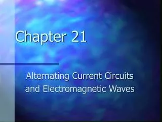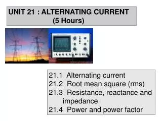
Alternating Current: Modulation and Transformers
Alternating Current: Modulation and Transformers. DC. In direct current (DC), the charge carriers (usually electrons) flow in one direction only. The size of the current (number of amps) may vary with time, but the flow direction does not.

Alternating Current: Modulation and Transformers
E N D
Presentation Transcript
DC • In direct current (DC), the charge carriers (usually electrons) flow in one direction only. • The size of the current (number of amps) may vary with time, but the flow direction does not. • A voltage that would cause a direct current in simple resistor circuit is called a DC voltage.
Voltage needs • Most computer hardware needs DC voltage, requiring between 1.5 and 13.5 volts. • A typical monitor, a cathode ray tube CRT display, requires much higher voltages.
AC/DC • Direct current is produced by batteries. • In contrast, the electricity available from the standard wall socket is alternating current (AC). • Less power is lost in transmitting high-voltage AC than in transmitting the corresponding amount using lower-voltage DC.
AC • Alternating current (AC) occurs when the charge carriers periodically reverse their direction. • Household current is AC with a frequency of 60 Hertz (cycles per second). • In some countries it is 50 Hz and a different voltage • The radio-frequency (RF) current in antennas and transmission lines is another example of AC.
Converting • AC can be converted to DC by a computer’s power supply. • A power supply consists of • a transformer (reduces voltage) • a rectifier (makes voltage positive only) • a filter (smoothes out voltage)
Waveform • The waveform is the shape of the voltage as a function of time • Typical AC waveforms can be • sinusoidal • square • sawtooth • ramped • triangular
Sinusoidal Peak voltage
Irregular • Ideally what comes out of a wall socket is sine-wave. • Square or sawtooth waves may be produced by some low-end uninterruptible power supplies when operating from the battery. • Some AC waveforms are irregular, particularly those carrying information • AC waves are produced by audio amplifiers that deal with analog voice signals and/or music.
Carriers and Modulation • One way to transmit information is to send it along with an AC current. • A simple sine wave conveys little to no information. • But one can modulate (change) the time dependence to send information • Amplitude modulation (AM) changes the peak value. • Frequency modulation (FM) changes the frequency. • Phase shift keying (PSK) changes the phase of the wave.
Amplitude: how big is the disturbance (esp. at its maxima) The two waves shown above have different amplitudes.
Frequency: how many cycles (one unit of repeated disturbance) go by in a second The two waves shown above have different frequencies.
Phase: what part of the cycle the wave is in at a particular time The above waves are “out of phase.”
Measuring AC voltage • An AC voltage is always changing with time. • The effective voltage of an AC power source is the DC voltage that would produce the same power dissipation (i.e amount of heat) for a simple resistor circuit. • This voltage is also known as the root-mean-square voltage.
RMS Versus Peak Voltages • Another way to characterize AC supplies is by their peak voltage, that is, the highest voltage in the shape. • The rms voltage is not equal to the peakvoltage. For a sine wave, the rms voltage is 0.707 times the peak voltage. • .707 1 / 2 • For example, if the typical US rms voltage is 117 V, then the typical peak voltage is 165 V.
Average Voltage • Sinusoidal AC voltage has the form • V(t) = Vpeak sin(2 f t), where • Vpeak is the peak voltage • f is the frequency • The average voltage is zero, • half the time it’s positive, half the time it’s negative
The Root Mean Square Average • The root mean square is a way to take a meaningful average • Square: the voltage is half negative,half positive. Square it so it will always be positive • Mean: average over time • Root: take the square root so we get back to voltage instead of voltage squared
Audio frequency • AC between 20 and 20,000 Hz is known as Audio frequency (AF). • If such current is fed into a speaker, it will produce sound waves within the range of human hearing. • All telephone circuits operate with AF signals in a restricted range of approximately 200 Hz to 3000 Hz.
Modem • Modems convert data in binary form into analog signals in the AF range that can be transmitted over the telephone wire • Modems also receive the AF signals and convert them back into binary form.
Limitations • The phone system was designed to work over a limited range of frequencies suitable to human voices • Humans hear 20-20,000 Hz • Phone system uses up to 3000 Hz • This limitation in frequencies puts limitations on bandwidth which is related to the rate of information flow. • The baud rate of a modem is tied to the frequencies phone lines were designed to handle.
Radio Frequencies • Radio frequency (RF) refers to an AC voltage that if applied to an antenna would produce an electromagnetic wave of the sort used in radio and other wireless communications.
Frequency range • These frequencies cover the portion of the electromagnetic spectrum, starting at around 9 kHz, and going up to thousands of gigahertz (GHz). • AM radio is between kHz and MHz. • FM radio is in the MHz range.
Wireless • Many wireless devices make use of RF fields. • Cordless and cellular telephone • Radio and television broadcast stations • Satellite communications systems • Two-way radio services • Some wireless devices operate at higher frequencies (Infrared IR or visible-light) frequencies • most television-set remote-control boxes • some cordless computer keyboards and mice
DSL • Digital Subscriber Line. • One choice to beat the limitations of modems. • It works at higher frequencies and hence higher bandwidths.
Ranges of RF • The RF spectrum is divided into several ranges, or bands. • The table shows the eight bands in the RF spectrum, along with their frequency and corresponding wavelengths. • The SHF and EHF bands are often referred to as the microwave spectrum.
Electricity and Magnetism • Changing electric fields cause magnetic fields. • Changing magnetic fields cause electric fields. • These effects lead to electromagnetic radiation (radio, microwaves, infrared, light, ultraviolet, x-rays). • They also lead to motors and transformers.
Transformers • Wires from two independent AC circuits are wound around a core (usually iron). • That’s why transformers are heavy. • A current is sent through the first (primary) circuit, producing a magnetic field in the core • Magnetic fields are caused by currents and changing electric fields. • That magnetic field is changing because the current is changing.
Transformers (Cont.) • The changing magnetic field in the core causes and electric field around the core. • That electric field causes a current in the other (secondary) circuit. • It too is an alternating current. • The voltages and currents are dependent on the number of times each is wrapped around the core.
Transformers (Cont.) • In this way the transformer changes the voltage. • Power=voltage current remains the same for the two circuits. • If the secondary voltage is lowered, it is known as a step-down transformer. • If the secondary voltage is raised, it is called a step-up transformer.


![SUBELEMENT T8 [4 Exam Questions – 4 Groups]](https://cdn0.slideserve.com/677287/subelement-t8-4-exam-questions-4-groups-dt.jpg)