1 / 36

Figure 3-1 Simple radio receiver block diagram.

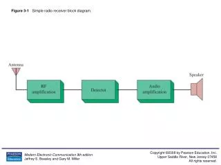
Figure 3-1 Simple radio receiver block diagram. Figure 3-2 Nonlinear device used as a detector. Figure 3-3 Diode detector. Figure 3-4 Diode detector component considerations. Dashed lines indicate average voltage during pulse.

Télécharger la présentation

Figure 3-1 Simple radio receiver block diagram.

An Image/Link below is provided (as is) to download presentation Download Policy: Content on the Website is provided to you AS IS for your information and personal use and may not be sold / licensed / shared on other websites without getting consent from its author. Content is provided to you AS IS for your information and personal use only. Download presentation by click this link. While downloading, if for some reason you are not able to download a presentation, the publisher may have deleted the file from their server. During download, if you can't get a presentation, the file might be deleted by the publisher.

E N D

Presentation Transcript


  1. Figure 3-1 Simple radio receiver block diagram.

  2. Figure 3-2 Nonlinear device used as a detector.

  3. Figure 3-3 Diode detector.

  4. Figure 3-4 Diode detector component considerations. Dashed lines indicate average voltage during pulse.

  5. Figure 3-5(a) A synchronous AM detector circuit as implemented in Electronics WorkbenchTM Multisim.

  6. Figure 3-5(b) The waveforms obtained from TP1 and TP2 for the synchronous AM detector provided in Figure 3-5(a).

  7. Figure 3-6 Superheterodyne receiver block diagram.

  8. Figure 3-7 Frequency conversion process.

  9. Figure 3-8 Frequency conversion.

  10. Figure 3-9 Variable ganged capacitor.

  11. Figure 3-10 Tracking considerations.

  12. Figure 3-11 Varactor diode symbols and C/V characteristic.

  13. Figure 3-12 Broadcast-band AM receiver front end with electronic tuning.

  14. Figure 3-13 Image frequency illustration.

  15. Figure 3-14 Image frequency not a problem.

  16. Figure 3-15 Dual-gate MOSFET RF amplifier.

  17. Figure 3-16 Typical mixer circuits.

  18. Figure 3-17 Typical IF amplifiers.

  19. Figure 3-17 (continued) Typical IF amplifiers.

  20. Figure 3-17(continued) Typical IF amplifiers.

  21. Figure 3-18 Development of AGC voltage.

  22. Figure 3-19 AGC circuit illustration.

  23. Figure 3-20 Wide-range IF/AGC amplifier. (Reprinted with permission from Electronic Design, Penton Publishing Company.)

  24. Figure 3-21 AM broadcast superheterodyne receiver.

  25. Figure 3-22 TDA1572T AM receiver. (Courtesy of Philips Semiconductors.)

  26. Figure 3-23 AM stereo block diagram.

  27. Figure 3-24 Phase relationships in AM stereo.

  28. Figure 3-25 C-Quam receiver system. (Courtesy of Motorola, Inc.)

  29. Figure 3-26 Receiver block diagram.

  30. Figure 3-27 Troubleshooting a self-excited mixer.

  31. Figure 3-28 Regulated power supply.

  32. Figure 3-29 Bridge rectifier and filter operating properly.

  33. Figure 3-30 Ripple increase caused by open diode.

  34. Figure 3-31 Testing an audio amplifier.

  35. Figure 3-32 An AM diode detector circuit as implemented with Electronics WorkbenchTM Multisim.

  36. Figure 3-33 Oscilloscope output traces from the diode detector.

More Related