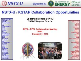
KSTAR Integrated Control System Overview
Learn about the KSTAR project, its operation and experiments, long-term phases, daily operations, and the control system architecture. The system features integration of controllers, archiving systems, and more.

KSTAR Integrated Control System Overview
E N D
Presentation Transcript
KSTAR Integrated Control System October 22, 2012 Mikyung Park
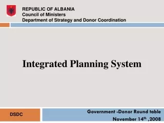
Introduction 1 • KSTAR Project • Operation and Experiments
KSTAR Project • KSTAR - Korea Superconducting TokamakAdvanced Research • Mission - • Development of a steady-state-capable advanced superconducting tokamakto establish the scientific and technological base for an attractive fusion reactor as a future energy source. • History- • 1995 : Project launched • 1998 : Construction started • 2007 : Completion of Assembly • 2008 : Achievement of the 1st plasma • 2012 : 5th Campaign SEOUL POHANG DAEJEON KSTAR NFRI
Tokamak and Ancillary Systems KSTAR Tokamak Motor Generator Cooling Water Heating Devices Cryogenic Refrigerator Diagnostics Magnet Power Supply Control Room
Operation and Experiments • About 6months/campaign/year • 6 Long-term Operation Phases / Campaign • Vacuum pumping – Cool down – Magnet test – Plasma Experiments – Warm up –Maintenance • Daily Operation • Search – Readiness check – TF on – Plasma shots – TF Off • Every plasma shot is identified by shot number Sequence Prepare for next shot Real-time control by PCS Create next shot # Plasma PF On PF Off Configuring parameter PFPS current=0? Data transferring Timing generation Parameter set DONE? @T0 • MPS Stop Processing & analysis Start of shot Shot Termination @T0 – 2min. • MPS run • PCS standby • MPS ready Lock Post activities • create shot summary • upload & visualize • shot results • send data, … Start of sequence End of sequence Create MDStree @T0 – 1min.
Sequential Operation for Plasma Exp. • Operator’s Panel Shot Sequences Synchronized operation
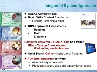
KSTAR Control System 2 • Features and architecture • Plant control and data acquisition system • Time and Synchronization System • Operator interfaces • Management tools
KSTAR Integrated Control Systems PlantControl Systems Operation/Experiments
_ Features • Using every possible Open-source Tools for development • Integration of Heterogeneous controllers • : PLC, cFP, VME, VXI, cPCI, PCI, PXI, PMC, FMC, ATCA • EPICS Release 3.14.8.2 ~3.14.12.2 • : But, Not 100%. A few systems have minimum interfaces. • : ~ 140 IOCs • Engineering data (managed by EPICS) • : ~ 60,000PVs, low rate & continuous • Experimental data (managed by MDSplus) • : ~ 11,600tags, high rate & pulse-based data • Two Archiving systems : EPICS Channel Archiver, MDSplus • Additional RDB : MSsql, Mysql • Standardization : design guideline, standard S/W framework • The control system is still growing !!
_ Architecture Plasma Control Supervisory/ Discharge Control Access Control Supervisory Interlock Data Analysis TokamakOperation *VM Client tools Visualization OPIs Control Network Storage Systems *VM *VM • Data Analysis • Server 1~2 • RDB • Server Standby 1~3 • CA • Gateway 1~6 Distributed Storage Image Storage GPFS SAN Lustre GPFS • Channel • Archiver1~2 • MDSPlus • Server 10G (1G) (2G) M E R I T • Main Storage • Disc Backup • Tape Backup GEP VMS/CLS/PMS HDS/GDS/CWF/MG TMS/ GCDS MPS HRS Heating Fueling Diagnostics PCS Sub-Interlock Plant Systems / EPICS IOCs Synchronized Operation Updated in Aug. 2012
_ Time and Synchronization System • Missions of Timing system • Synchronized operation and experiments according to the sequences • Hardware triggering (including clocks) along w. GPS time using timing board • Provision of reference time data to all computers at KSTAR • NTP (Network Timing Protocol) • 3. Additionally, it must provide multiple triggering during a shot, • to support long pulse operation • to efficiently manage data generated during plasma shot Synchronization Central Timing System GPS Antenna CTU (Central Timing Unit) Calibration IRIG-B DCLS GPS Receiver L1, 1.575GHz 2Gbps NTP Rubi Source REF IN Optical SW 10MHz (1x10-11/month) LTU (Local Timing Unit) ~40 being used F/O : 850nm, Multi-mode • Mikyung Park et. al, “The upgrade of KSTAR timing system to support long pulse operation and high-speed data acquisition”, • Fusion Engineering and Design Vol.87 (2012)
_ Time and Synchronization System CLTU Timing Board Extension Module Max. 8 configurable sections /shot 2V/div 100ms/div RIN=1MW Trigger Clock
_ Operator Interfaces • KSTAR Widget Toolkit (KWT)
_ Operator Interfaces • KSTAR Widget Toolkit (KWT) • Sulhee Baek, et.al “Development status of KSTAR Widget Toolkit (KWT)”, 2010 Spring EPICS Collaboration Meeting, France • Sangil Lee, et. al, “Operator Interface Programs for KSTAR Operation”, 2011 IAEA TM, San Francisco, USA
_ Management Tools and Utilities • Monitoring of control system and supporting experiments VM Player or freeware X-manager OfficeNetwork • Office • Gateway Read only Machine Network Exp. Data Network • Woongryol Lee “Application of rt-patched EPICS for real-time monitoring”, 2012 Fall EPICS meeting, Oct.23(Tue), 2012, 13:30-13:40 KSTAR Exp. Zone
Control System Monitoring Developed Several Modules: Network Status: Using Internet Control Message Protocol Storage/Switch: Using Simple Network Management Protocol Two Widgets: BlinkLine, CABlinkLabel for User Interface Environment Monitoring: Using NI’s Compact Field Point sysMonLib with EPICS Lib in All IOC Servers and IT Servers Itself Monitoring Resources in Each Server (CPU, Memory, Used Network Packet, and so on) Virtualization for KSTAR IT Infrastructure Using VMWare (ESX / ESXi) Can use ESXi Hypervisor for free (Not support vMotion and Fault Tolerant) Commercially ESX Hypervisor _ Management Tools and Utilities ※ Sangil Lee, et. al, “Management Tools for distributed control system in KSTAR”, 13th ICALEPCS, France (2011)
Data Sharing and User Services 3 • Services for on- and off-site users • Data sharing with collaborators
Environment for Data Sharing • Transferring Data file • ~ 2011 : send experimental data to collaborator in U.S at every shot • ~140MB, compressed data using FTP (GridFTP) thru non-Gloriad net • Drawback : ~8min, sometimes 10min ~ 20min • As an alternative : • Using GLORIADand a commercial fast file transferring solution (ASPERA) • Test results : decreased to 7sec at a maximum BW • Future plan : Establish the KSTAR data center at NFRI • Access to KSTAR Data for general users • A gateway server and a virtual desktop tool (NoMachine)
Services of Experimental Info Shot Info 7435
Summaries and Conclusions 4 • Encountered Problems and Issues • Summaries and Conclusions
Encountered Problems and Issues • Sometimes unstable CA connection and operation of Cagateway due to heavy UIs • ArchiveViewer • Drawbacks to display data for long time history due to lack of cache • It takes long time to move to CSS • Implantation of unified environment for managing whole control system • Many home-made and other tools • Poor interconnection between them • Decision of new standard data format for bid experimental data • Not related to EPICS, but big issue for coming experiments
Encountered Problems and Issues • Solution for Heavy Traffics of UIs Cached Channel Access Algorithm in KWT • Possible Problems for a lot of CA Connections • Network Bandwidth due to Network Packet Increasing • - Use a lot of same OPI programs by multiple users on a single host • - Use a lot of OPI programs by one user • Limited Socket Descriptor Count of Gateway Server • : “select” used in gateway has the limited file descriptor count, 1024 • To Solve the Problems => “Cached Channel Access” • Shared Memory Based Hash Table • Decreasing Network Packet Volume • Decreasing Socket Descriptor Count Between OPIs and Gateway server
Conclusions • The EPICS-based KSTAR control system has proved its performance and reliability for last 4 campaigns. • Now, we encounter the lack of performance of infrastructure like resources of servers, storage capacity and network bandwidth too. • We will apply the standard rules more strictly for increasing the availability of control systems. • We will also focus on the upgrade of control system to support long pulse experiments.