Download
1 / 20
200 likes | 367 Vues
General work on the DAQ system - From the slab backwards …. Cambridge University Imperial College London University of Manchester Royal Holloway, University of London University College London Matthew Warren, UCL 13 February 2007. Overview. 1. CALICE-DAQ 2. Optical Switch

E N D
General work on the DAQ system - From the slab backwards … Cambridge University Imperial College London University of Manchester Royal Holloway, University of London University College London Matthew Warren, UCL 13 February 2007
Overview • 1. CALICE-DAQ • 2. Optical Switch • 3. Single Event Upsets CALICE - DAQ
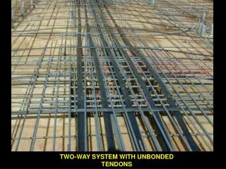
DAQ Structural Overview • ASICs • Front-End (FE) • FE-Interface (DIF): Detector specific • FE Link/Data Aggregator (LDA): Generic • Data-link (FE to Off-Detector Receiver) • Control-link (C+C to FE) • DAQ PC • Off-Detector Receiver (ODR) • Control data-link (Clock, Control to FE) • Data Store ASICs DIF FE LDA Data-link Control-link PC/s ODR Store CALICE - DAQ
FE Structure Detail • We have 2+ types of detector to readout. • Divide the FE into a 2 part, tiered system • 1) Detector Interface module (DIF) • Detector specific interface • Includes power connectors • ‘Local’ systems (e.g. clock) • Debug connectors • 2) Link/Data Aggregator module • (LDA) • Collects data from many ‘DIF’s • Drives data Off detector link • Receives and distributes C+C • BUT: • We would probably like to read-out slabs individually first… ECAL Slab ECAL Slab HCAL Layer HCAL Layer ECAL Interface ECAL Interface HCAL Interface HCAL Interface Link/ Data Aggregator Link/ Data Aggregator PC PC CALICE - DAQ
Detector Detector FE – More thoughts • Each DIF can connect directly to an LDA for stand-alone operation • OR • Combine on single PCB, with single FPGA • Capabilities depend on PCB loading • Operate as stand-alone, or as master-slave (aggregator) • Firmware development 2 tiered • Eg: ECAL: Slave-Out FPGA Local Control In Opto Detector Fibre Slab connector Power In Slaves-In CALICE - DAQ
Data-link (+Control) • Plan to use most common networking fibre-optics: • Multimode with LC connectors • SFP (mini-GBIC) interfaces • 1Gbit rate • Ethernet • Control up-link NOT via fibre, initially. CALICE - DAQ
Off-Detector Receiver (ODR) • PCI Express Card • Virtex 4, FX100 FPGA (big!) • Hosts opto-links • 2xSFP, 2xHSSDC2 on board • Source of C+C (Control link) • Initially copper (SMA connectors?) • Later fibre • Will use external clock and sync signals for multi-PC operation CALICE - DAQ
ODR(2) - Status • Firmware AND software well underway: • PCIe interface DONE • Register read/write DONE • DMA access DONE • Ethernet Interface • IN-PROGRESS • DDR2 Interface IN-PROGRESS • Linux driver DONE • Manager Software • IN-PROGRESS • Performance profiling • IN-PROGRESS • Clock and Control Uplink • NOT-STARTED Ethernet Interface DDR2 Interface Test Data Gen Arbiter Internal RAM PCIe Interface Control/ Status Reg. Block Firmware Driver Manager Software CALICE - DAQ
Datastore and Integration • Keep it simple! • Event files written to local disk • System synchronising signals distributed • All data tagged with common ‘timestamp’ PC Fanout Clock ODR ODR Command (Train-start, Sync) Fanout PC ODR ODR CALICE - DAQ
UK Read-out work (ECAL FE) • Detector Interface (Cam) • Spec + hardware • DIF to Link/Data Aggregator (Cam/Man) • Spec + hardware • Data aggregate, format (Man) • Hardware + firmware • LDA to ODR opto-link (Man, UCL) • Hardware + firmware • ODR (RHUL, UCL, Cam) • firmware • ODR to disk (RHUL) • Driver software • Local Software DAQ (RHUL) • Full blown Software DAQ (RHUL, UCL, [IC]) ECAL Slab DIF LDA Opto PC ODR Opto Driver CALICE - DAQ
DAQ Summary • UK proposes to do large part of readout chain • [we can fight independently!] • Key areas for development identified: • Baseline structure • Work segmented • ECAL will be looked after entirely by UK • HCAL may need to manufacture own FE PCB CALICE - DAQ
Optical Switch CALICE - DAQ
Optical (Layer-1) Switching • Part of the UK project is to evaluate the use of a “layer-1” switch. • This switch physically (re)connects fibres • It can be used in various ways: • DAQ PC failover • Redirect data to spare unused DAQ PC on the fly • 2) “Router” (able to switch at >10Hz for many years) • Can change data destination per bunch-train. • Regulate load by sending data directly to free resources • 3) Programmable optical patch panel (large installation) • Easily switch to redundant fibres remotely • Useful for grouping fibres from physics region (e.g. logical grouping) CALICE - DAQ
Switch Unit Purchased • Manufacturers offering similar products, in same price range e.g. Glimmerglass, Polatis - difficult to differentiate between them • Decided on Polatis • can switch dark fibre (i.e. not MEMS based) • Multimode fibre capable • Fastest switching time (20ms) • 16x16 array with 50μm multimode LC connectors CALICE - DAQ
Single Event Upset Studies CALICE - DAQ
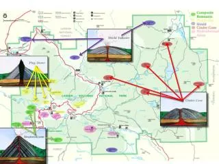
Single Event Upsets • Attempting to find out expected SEU rates in FE • Influences choice of technology for final FE • Influences re-configure/reset rate of FE • SEU rates very dependent on hardware, and we have none! • Attempting to provide framework and data for use when making hardware decisions later • We have simulated the expected environment at the end of ECAL slabs. • Results are compared with existing FPGA measurements. CALICE - DAQ
SEU: Energy Spectrum of Particles in FPGAs Y axis: hits/hour QCD Valeria Bartsch WW ttbar CALICE - DAQ
SEU: Weibull Fit • above 20MeV neutrons start doing upsets IEEE Transactions on Nuclear Science Vol. 50, No.2, 2003 Gingrich CALICE - DAQ
SEU: Rates expected with existing FPGAs • in best case 1 SEU in 8 days for all FPGAs in the ECAL CALICE - DAQ
Fin … CALICE - DAQ