Introduction to AC Circuits: Understanding Voltage, Complex Notation, and Phasor Diagrams
80 likes | 195 Vues
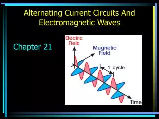
This mini-lecture introduces the fundamentals of AC circuits, focusing on AC voltage, which varies with time as v(t) = V0cos(ωt). Learn about complex voltage representation, using the notation v = V0ejωt to illustrate how voltage can be modeled as a vector quantity. We explore the application of Ohm's Law in AC circuits and the concept of internal resistance through Thévenin equivalent circuits. Additionally, gain insights into phasor diagrams, which visually represent complex numbers and reveal the relationship between AC current and voltage.

Introduction to AC Circuits: Understanding Voltage, Complex Notation, and Phasor Diagrams
E N D
Presentation Transcript
ADV/TEC 2: Introducing AC Circuits Introductory mini-lecture
AC Voltage • Voltage varies with time: v(t) = V0cos(ωt) • V0is the voltage amplitude • v(t) is the instantaneous voltage • ω=2πf is the angular frequency (in radians/s)
Complex Notation • We define a complex voltage v =V0ejωt = V0cos(ωt) + jV0sin(ωt) where (we use j because i is used for current) • Complex notation is a convenient mathematical model for vector quantities • The instantaneous voltage is the real part of the complex voltage
Resistors in AC Circuits • Ohm’s Law still holds for resistors in AC circuits • If the supplied voltage to a resistor is v =V0ejωt, then the current through the resistor is i= v/R = (V0/R)ejωt = I0ejωt
Internal Resistance • All real signal sources can be represented by an ideal source in series with a resistor (internal resistance). This combination is called the Théveninequivalent circuit.
Phasor Diagrams • We represent complex numbers graphically by Argand diagrams: x-axis is the real part, y-axis is the imaginary part • Complex voltage v =V0ejωt is then a vector that rotates counter-clockwise with time • Instantaneous voltage is its projection onto the x-axis
Phasor Diagrams Yellow= voltage Green= current Note that current and voltage are in phase


![Introducing K2 [blackpearl] BPM](https://cdn0.slideserve.com/1221291/introducing-k2-blackpearl-bpm-dt.jpg)