Download
1 / 20
200 likes | 221 Vues
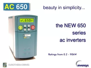
Discover the simplicity of the new AC 650 series inverters, ranging from 0.2kW to 90kW. These inverters are designed to be simple to install, set up, and operate, with no programming languages to learn and an easy-to-navigate menu. The AC 650 is small in size but long on features, offering built-in EMC compliant filters, pre-programmed applications, and compact frame options. With flexible inputs and outputs, simple operator controls, and application presets, the AC 650 is suitable for various applications like material conveyors, fans, pumps, and more. Enjoy easy tuning for different load types with selectable v/f curves and straightforward programming options. Get ready to experience seamless operations and efficient control with the AC 650 inverters.

E N D
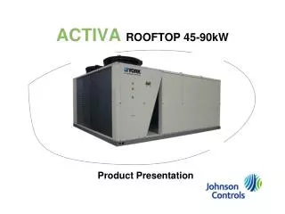
AC 650 beauty in simplicity... the NEW 650 series ac inverters Ratings from 0.2 - 90kW
AC 650 … simple to install … simple to set-up … simple to operate • no programming languages to learn • easy to navigate menu • ready-to-go from the box
AC 650 small in size… … long on features • built-in EMC compliant filters (up to 7.5kW, footprint >7.5kW) • DIN rail or direct panel mounting (up to 7.5kW) • pre-programmed applications
AC 650 3 new compact frames 1 230V 1ph .2kW .37kW .55kW .75kW H W D (mm) 137 73 142 H W D (mm) 192 73 173 H W D (mm) 257 96 195 3 230V 1ph 400V 3ph .37kW 1.1kW .55kW 1.5kW .75kW 1.1kW 1.5kW 2.2kW 2 2 3 400V 3ph 3.0kW 4.0kW 5.5kW 7.5kW 1
AC 650 above …7.5kW F E D C 11(15) KW 15(18.5)-22(30) KW 30(37)-45(55) KW 55(75)-90(110) KW All New Bookshelf Frames 380-460V 3.0-7.5 KW 3 2 1 230V 1.1-1.5 KW 380-460V .37-2.2 KW 230V .25 -.75 KW 380-460V (Ratings In Brackets) = Quadratic “Fan” Torque …up to 7.5kW
AC 650 flexible inputs & outputs ONE option provides two features - Remote-mount keypad together with P3 comms port CONTROL POWER volt-free relay contacts • digital I/O • 8 presets • 2 programmable I/O motor thermistor AC line input • analogue I/O • 0 - 10V or 4-20mA input • 1 programmable output • for load or speed motor
AC 650 simple operator controls Backlit LCD display Speed, Hz, or units Rotation local /remote START STOP Locally mounted & removable orRemote-mount option program menu raise / lower speed
AC 650 simple & easy ...for all your applications VT (Variable Torque) CT (Constant Torque) material conveyors fans & blowers batch mixers centrifugal pumps
AC 650 V CONSTANT TORQUE VARIABLE TORQUE f simple tuning for your load type Selectable v/f curves match your load requirement VT Vbase CT fbase
AC 650 simple programming Directions on cover back • Application selection parameter! • Menu navigation • Set-up parameters • Diagnostics • Fault codes
AC 650 p Applications 1 basic speed control 01 automatic/ manual02 raise/ lower04 Application 2, automatic/manual - STANDARD PARAMETER LIST - with auto / manual control input selection simple application programming preset speeds 03 PI control05 Application 3, preset speeds STANDARD PARAMETERS p301 Preset 0 Application 5, PI p1 APPLICATION (1-5) p501 P gain : : p2 Max speed p502 I gain p308 Preset 7 p3 Min Speed p4 Accel time p5 Decel time p6 Motor rated current p7 Base frequency Application 4, raise/lower p8 Jog setpoint p401 Ramp time p9 Stop mode p402 Max value p11 V/F shape p403 Min value p12 HVAC ratings p404 Reset value p13 Fixed boost, (VF only) p99 Password
AC 650 STANDARD PARAMETERS p1 APPLICATION (1-5) p2 Max speed p3 Min Speed p4 Accel time p5 Decel time p6 Motor rated current p7 Base frequency p8 Jog setpoint p9 Stop mode p11 V/F shape p12 HVAC ratings p13 Fixed boost, (VF only) p99 Password Application 3, presets p301 Preset 0 : : p308 Preset 7 Application 4, raise/lower p401 Ramp time p402 Max value p403 Min value p404 Reset value Application 5, PI p501 P gain p502 I gain menu structure DIAG Diagnostics PAR Parameters SET Setup TRIP Disabled Trips d1 Frequency (Hz) IN Inputs (p1=1) d2 Speed setpoint (%) IP01 Digin 1 invert LOOP Anin2 input break IP02 Digin 2 invert d3 DC Link volts(v) T 3 Anin2 overload IP03 Digin 3 invert STLL Stall d4 Motor current (A) IP04 Digin 4 invert OT Motor over temp IP11 Anin 1 scale DB R Brake resistor IP12 Anin 1 offset DB S Brake switch IP13 Anin 1 type OP Op station IP21 Anin 2 scale IP22 Anin 2 offset SET Setup IP23 Anin 2 type ST01 Jog accel time APPLICATION PARAMETERS OUT Outputs ST02 Jog decel time OP01 Anout select ST03 Ramp type p1= 2 Application 2, automatic/manual OP02 Anout scale - STANDARD PARAMETER LIST - ST04 S-ramp jerk OP03 Anout offset ST05 S-ramp continuous OP04 Anout abs p1= 3 APPLICATIONPARAMETERS appear only when selected ST11 Skip frequency 1 OP11 Digout 1 select ST12 Skip freq band 1 OP12 Digout 1 invert OP21 Digout 2 select ST13 Skip frequency 2 OP22 Digout 2 invert ST14 Skip freq band 2 OP31 Relay select p1= 4 ST21 Auto restart attempts OP32 Relay invert ST22 Auto restart delay ST23 Auto restart triggers SERL Serial Comms ST24 Auto restart triggers+ p1= 5 SE01 Remote comms sel ST31 Dynamic brake enable SE02 Comms timeout ST32 DB resistance SE03 Address ST33 DB power SE04 Modbus baud rate ST34 DB over-rating SE05 Modbus parity
Application 1 : Basic Speed Control STANDARD PARAMETERS P1 APPLICATION = 1 p1 Application p2 Max speed p3 Min Speed DIAGNOSTICS p4 Accel time d1Frequency Hz d2 Speed Setpt % d3DC Link Volts V d4Motor I A p5 Decel time p6 Motor rated current p7 Base frequency p8 Jog setpoint p9 Stop mode p11 V/F shape p12 HVAC ratings P2 MAX SPEED IP13 AIN1 TYPE p13 Fixed boost, (VF only) p99 Password REFERENCE SELECT 0 0-10V 1 0-5V IP23 AIN2 TYPE P8 JOG SPD 0 0-10V 1 0-5V 2 0-20mA 3 4-20mA OP01 ANOUT SEQUENCING LOGIC PWM CONTROL V/F SHAPING 0 NONE 1 HEALTH 2 TRIPPED 3 RUNNING 4 AT ZERO 5 AT SPEED OP21 DIGIO2 P13 V BOOST P9 STOP MODE P7 BASE FREQ RL1A RL1B 0 NONE 1 HEALTH 2 TRIPPED 3 RUNNING 4 AT ZERO 5 AT SPEED User Relay 60Hz base frequency R P11 V/F SHAPE OP31 RELAY 0 = CONSTANT TORQUE 1 = VARIABLE TORQUE IDEAL FOR GENERAL PURPOSE APPLICATIONS, CONSTANT TORQUE AND VARIABLE TORQUE P4 ACCEL TIME Feedback 4-20mA 0V AIN1AIN2+10V REF AOUT1 +24V DIN1 DIN2 DIGIO1 DIGIO2 MIN/MAX SPEED 1 2 3 4 5 6 7 8 9 10 RAMP FWD/REV SPEED DEMAND Ref. P3 MIN SPEED P5 DECEL TIME 0 NONE 1 DEMAND% 2 CURRENT% 3 PID ERROR% 4 RAISE/LOWER% I FDBK CURRENT LIMIT START V V FWD/REV V CT VT JOG F F F STOP P6 I NOMINAL *BLUE is DEFAULT
Application 2 : Auto / Manual Control STANDARD PARAMETERS P1 APPLICATION = 2 p1 Application p2 Max speed p3 Min Speed DIAGNOSTICS p4 Accel time d1Frequency Hz d2 Speed Setpt % d3DC Link Volts V d4Motor I A p5 Decel time p6 Motor rated current p7 Base frequency p8 Jog setpoint p9 Stop mode p11 V/F shape p12 HVAC ratings P2 MAX SPEED IP13 AIN1 TYPE p13 Fixed boost, (VF only) p99 Password MIN/MAX SPEED REF SELECT 0 0-10V 1 0-5V 2 0-20mA 3 4-20mA P3 MIN SPEED SEQUENCING LOGIC PWM CONTROL V/F SHAPING 0 NONE 1 HEALTH 2 TRIPPED 3 RUNNING 4 AT ZERO 5 AT SPEED OP21 DIGIO2 P13 V BOOST P7 BASE FREQ RL1A RL1B 0 NONE 1 HEALTH 2 TRIPPED 3 RUNNING 4 AT ZERO 5 AT SPEED User Relay 60Hz base frequency R P11 V/F SHAPE OP31 RELAY 0 = CONSTANT TORQUE 1 = VARIABLE TORQUE IDEAL FOR AUTOMATIC CONTROL APPLICATIONS WITH LIMIT SWITCHES OR PROXIMITY TRANSDUCERS P4 ACCEL TIME AUTO REF 0V AIN1AIN2+10V REF AOUT1 +24V DIN1 DIN2 DIGIO1 DIGIO2 0 0-10V 1 0-5V 1 2 3 4 5 6 7 8 9 10 RAMP FWD/REV SPEED DEMAND IP23 AIN2 TYPE MAN. REF P5 DECEL TIME P9 STOP MODE P9 STOP MODE I FDBK MAN. RUN CURRENT LIMIT V V AUTO RUN V CT VT MAN./AUTO RUN SELECT F F F FWD / REV P6 I RATED *BLUE is DEFAULT
Application 3 : Preset Speeds STANDARD PARAMETERS P1 APPLICATION = 3 p1 Application IP300 PRESET 0 p2 Max speed p3 Min Speed DIAGNOSTICS IP301 PRESET 1 p4 Accel time d1Frequency Hz d2 Speed Setpt % d3DC Link Volts V d4Motor I A p5 Decel time IP302 PRESET 2 p6 Motor rated current p7 Base frequency IP303 PRESET 3 p8 Jog setpoint IP304 PRESET 4 p9 Stop mode p11 V/F shape P2 MAX SPEED IP305 PRESET 5 p12 HVAC ratings p13 Fixed boost, (VF only) IP306 PRESET 6 p99 Password MIN/MAX SPEED IP307 PRESET 7 P3 MIN SPEED DIGIO2 DIGIO1 DIN2 PRESET 0V 0V 0V 0 0V 0V 24V 1 0V 24V 0V 2 PWM CONTROL V/F SHAPING 0V 24V 24V 3 24V 0V 0V 4 24V 0V 24V 5 24V 24V 0V 6 24V 24V 24V 7 P13 V BOOST P7 BASE FREQ RL1A RL1B 0 NONE 1 HEALTH 2 TRIPPED 3 RUNNING 4 AT ZERO 5 AT SPEED User Relay 60Hz base frequency R P11 V/F SHAPE P9 STOP MODE P9 STOP MODE OP31 RELAY 0 = CONSTANT TORQUE 1 = VARIABLE TORQUE IDEAL FOR APPLICATIONS WHERE MULTIPLE DISCRETE SPEED LEVELS ARE REQUIRED (SCALABLE) AUTO REF P4 ACCEL TIME 0V AIN1AIN2+10V REF AOUT1 +24V DIN1 DIN2 DIGIO1 DIGIO2 1 2 3 4 5 6 7 8 9 10 RAMP FWD/REV SPEED DEMAND SPEED DEMAND MAN. REF P5 DECEL TIME I FDBK START/STOP CURRENT LIMIT V V PRESET IN V CT VT PRESET IN F F F PRESET IN SEQUENCING LOGIC P6 I NOMINAL *BLUE is DEFAULT
Application 4 : Raise/Lower STANDARD PARAMETERS P1 APPLICATION = 4 p1 Application p2 Max speed p3 Min Speed DIAGNOSTICS p4 Accel time d1Frequency Hz d2 Speed Setpt % d3DC Link Volts V d4Motor I A p5 Decel time p6 Motor rated current p7 Base frequency p8 Jog setpoint p9 Stop mode p11 V/F shape P2 MAX SPEED p12 HVAC ratings p13 Fixed boost, (VF only) p99 Password MIN/MAX SPEED P3 MIN SPEED PWM CONTROL V/F SHAPING P13 V BOOST P7 BASE FREQ RL1A RL1B 0 NONE 1 HEALTH 2 TRIPPED 3 RUNNING 4 AT ZERO 5 AT SPEED User Relay 60Hz base frequency R P11 V/F SHAPE P9 STOP MODE P9 STOP MODE OP31 RELAY 0 = CONSTANT TORQUE 1 = VARIABLE TORQUE IDEAL FOR APPLICATIONS WHICH REQUIRE SPEED CONTROL FROM MULTIPLE LOCATIONS P4 ACCEL TIME 0V AIN1AIN2+10V REF AOUT1 +24V DIN1 DIN2 DIGIO1 DIGIO2 RAISE / LOWER 1 2 3 4 5 6 7 8 9 10 RAMP FWD/REV SPEED DEMAND SPEED DEMAND P5 DECEL TIME SEQUENCING LOGIC I FDBK P401 RAMP TIME START/STOP CURRENT LIMIT V P402 MAX VALUE V RAISE V P403 MIN VALUE CT VT LOWER P404 RESET VALUE F F F RESET P6 I NOMINAL *BLUE is DEFAULT
Application 5 : PID Control STANDARD PARAMETERS P1 APPLICATION = 5 p1 Application p2 Max speed p3 Min Speed DIAGNOSTICS p4 Accel time d1Frequency Hz d2 Speed Setpt % d3DC Link Volts V d4Motor I A p5 Decel time p6 Motor rated current p7 Base frequency p8 Jog setpoint p9 Stop mode p11 V/F shape p12 HVAC ratings p13 Fixed boost, (VF only) p99 Password REFERENCE SELECT P8 JOG SPD OP01 ANOUT 0 NONE 1 DEMAND% 2 CURRENT% 3 PID ERROR% 4 RAISE/LOWER% PWM CONTROL V/F SHAPING P13 V BOOST P7 BASE FREQ RL1A RL1B 0 NONE 1 HEALTH 2 TRIPPED 3 RUNNING 4 AT ZERO 5 AT SPEED User Relay 60Hz base frequency R P11 V/F SHAPE OP31 RELAY 0 = CONSTANT TORQUE 1 = VARIABLE TORQUE EASY TUNING FOR SETPOINT/ FEEDBACK CONTROL APPLICATIONS, REGULATING VOLUME OR PRESSURE, SUCH AS AIR HANDLING OR PUMPING P501 P GAIN P502 I GAIN P2 MAX SPEED P4 ACCEL TIME Feedback 4-20mA 0V AIN1AIN2+10V REF AOUT1 +24V DIN1 DIN2 DIGIO1 DIGIO2 PID CONTROL MIN/MAX SPEED 1 2 3 4 5 6 7 8 9 10 RAMP FWD/REV SPEED DEMAND Ref. P3 MIN SPEED P5 DECEL TIME SEQUENCING LOGIC I FDBK CURRENT LIMIT START V V FWD/REV V CT VT JOG F F F STOP P9 STOP MODE P6 I NOMINAL *BLUE is DEFAULT
mount more drives per cabinet! AC 650 DIN rail mount on frames 1-3 No side ventilation allows for zero clearance between drives! VENTILATION
AC 650 the NEW 650 series ac inverters simple… smart… easy…
AC 650 the NEW 650 series ac inverters Thank you for your attention. Any Questions ?
![Altitude= [0.2, 4.0km]](https://cdn4.slideserve.com/464372/nasa-s-cloud-absorption-radiometer-dt.jpg)