Sheet Metal Shearing Processes in Manufacturing
680 likes | 702 Vues
Learn about shearing in sheet metal processing, from punch and die operations to fine blanking and slitting techniques. Explore variables, effects, and best practices.

Sheet Metal Shearing Processes in Manufacturing
E N D
Presentation Transcript
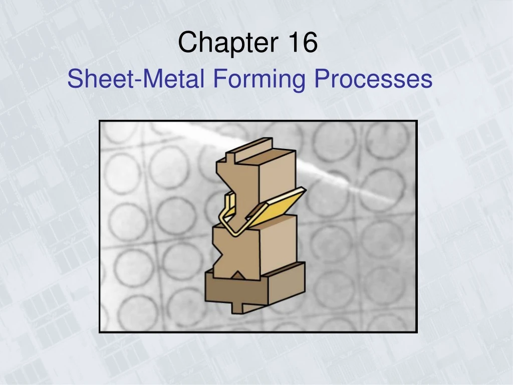
Sheet-Metal Forming Processes Chapter 16
Sheet-Metal Parts (a) (b) Figure 16.1 Examples of sheet-metal parts. (a) Die-formed and cut stamped parts. (b) Parts produced by spinning. Source: (a) Courtesy of Aphase II, Inc. (b) Courtesy of Hialeah Metal Spinning, Inc.
Shearing • Shearing: mechanical cutting of materials without the formation of chips or the use of turning or melting. • Shearing starts with the formation of cracks on both top & bottom edges of wp (A, B, C, D). • Shearing parameters: • Shape of & materials for punch and die. • Punching speed. • Lubrication • Clearance, c, between punch & die. As c inc, the sheared edge becomes rougher, and the zone of deformation becomes larger (F16.2)
Shearing with a Punch and Die Figure 16.2 (a) Schematic illustration of shearing with a punch and die, indicating some of the process variables. Characteristic features of (b) a punched hole and (c) the slug. (Note: The scales of the two figures are different.)
Shearing • Ratio of burnished to rough areas on sheared edge increases with increasing ductility of sheet metal, and decreases with increasing sheet thickness & clearance. • c = 2-10% of the sheet thickness. • As the punch speed increases, heat generated by plastic deform is confined to smaller zone; therefore the shear zone is narrower, and the surface is smoother and exhibits less burr formation. • Burr height increases with increasing clearance and ductility of sheet metal. • Edge quality improve with increasing punch speed (10-12m/s) Figure 16.3 (a) Effect of the clearance, c, between punch and die on the deformation zone in shearing. As the clearance increases, the material tends to be pulled into the die rather than be sheared. In practice, clearances usually range between 2 and 10% of the thickness of the sheet. (b) Microhardness (HV) contours for a 6.4-mm (0.25-in.) thick AISI 1020 hot-rolled steel in the sheared region. Source: After H.P Weaver and K.J. Weinmann.
Shearaing Force and Shearing Operations • Max Punch force, F = 0.7 TL(UTS) • Where: T = sheet thickness, L = total sheared length. • As clearance increases, punch force decreases, and wear on dies & punches decreases. • Shearing operations • Die cutting: a shearing process that consists of the following operations (F16.4): Perforating – parting – notching – lancing. Figure 16.4 (a) Punching (piercing) and blanking. (b) Examples of various die-cutting operations on sheet metal.
Shearing Operations 2 • Piercing - The typical punching operation, in which a cylindrical punch pierces a hole into the sheet. • Slotting - A punching operation that forms rectangular holes in the sheet. Sometimes described as piercing despite the different shape. • Perforating - Punching a close arrangement of a large number of holes in a single operation. • Notching - Punching the edge of a sheet, forming a notch in the shape of a portion of the punch. • Nibbling - Punching a series of small overlapping slits or holes along a path to cutout a larger contoured shape. This eliminates the need for a custom punch and die but will require secondary operations to improve the accuracy and finish of the feature. • Lancing - Creating a partial cut in the sheet, so that no material is removed. The material is left attached to be bent and form a shape, such as a tab, vent, or louver. • Slitting - Cutting straight lines in the sheet. No scrap material is produced. • Parting - Separating a part from the remaining sheet, by punching away the material between parts. 1 3 4 5 6 7 8
Fine-Blanking • Very smooth and square edges can be produced by fine blanking (Fig. 16.5a). • A V-shaped stinger or impingement mechanically locks the sheet tightly in place and prevents the type of distortion of the material shown in Figs. 16.2b and 16.3. • Clearances: 1% sheet thick, Sheet thick: 0.5 to 13mm, Dim tolerances: ±0.025 – 0.05mm Figure 16.5 (a) Comparison of sheared edges produced by conventional (left) and by fine-blanking (right) techniques. (b) Schematic illustration of one setup for fine blanking. Source: Courtesy of Feintool U.S. Operations.
Slitting • Slitting (F16.6): blades follow either a straight line or circular or curved path. • Two types of slitting equipment: • Driven type: powered blades. • Pull-through type: strip is pulled through idling blades Figure 16.6 Slitting with rotary knives. This process is similar to opening cans.
Steel Rules and Nibbling Steel Rules: • Soft metals (as Well as paper, leather, and rubber) can be blanked with a steel-rule die. • The die consists of a thin strip of hardened steel bent into the shape to be produced. • The die is pressed against the sheet, which rests on the flat surface, and it shears the sheet along the shape of the steel rule. Nibbling: • a machine called a nibbler moves a small straight punch up and down rapidly into a die. • A sheet is fed through the gap and many overlapping holes are made which forms the desired path. • Very high flexibility and intricate slots and notches can be made. • Economical for small production runs because of no special dies and punches.
Tailor-Welded Blanks Scrap in shearing: as high as %30 on large stampings. Scrap can be reduced by proper arrangement the shapes on the sheet to be cut (nesting) Figure 16.7 Production of an outer side panel of a car body by laser butt-welding and stamping. Source: After M. Geiger and T. Nakagawa.
Characteristics and Type of Shearing Dies • Clearances: depend on • Type of material, its temper • Thickness and size of blank • Blank’s proximity to edges of original sheet • The thicker the sheet is, the larger the Clearances must be. • Small holes require more clearance than larger ones. • Clearance range: 2-8% typical, may be as small as 1% or as large as 30%. • Shaving process (F16.9): extra material from rough sheared edges is trimmed. • As a general guidelines, a) clearances for soft materials are less than those for harder grades; (b) the thicker the sheet, the larger the clearance must be; and (c) as the ratio of hole diameter to sheet thickness decreases, clearances should be larger.
The Shaving Process Figure 16.9 Schematic illustrations of the shaving process. (a) Shaving a sheared edge. (b) Shearing and shaving combined in one stroke.
Shear Angles Punch & die shape: beveling suitable for shearing thick blanks, because it reduces force at beginning of stroke, lower noise. Figure 16.10 Examples of the use of shear angles on punches and dies.
16.2 Shearing - Dies • Compound dies: several operations on the same strip performed in one stroke at one station (F16.11). • Simple shapes are made because the process is slow and the dies become much more expensive. • Progressive dies: sheet metal is fed through as coil strip, and different operation is performed at the same station with each stroke of a series of punches (F16.11c). • Transfer dies: sheet metal undergoes different operations at different stations, which are arranged along straight line or circular path. • Tool & die materials: tool steels for shearing, carbides for high production rates
Compound Die and Progressive Die Figure 16.11 Schematic illustrations: (a) before and (b) after blanking a common washer in a compound die. Note the separate movements of the die (for blanking) and the punch (for punching the hole in the washer). (c) Schematic illustration of making a washer in a progressive die. (d) Forming of the top piece of an aerosol spray can in a progressive die. Note that the part is attached to the strip until the last operation is completed.
Miscellaneous Methods of Cutting Sheet Metal • Band saw –metal material removal process that produces chips as in other machining • Flame cutting –especially for thick steel plates, as in shipbuilding • Laser-beam cutting –newer process used with computer controlled equipment • Plasma cutting –high energy plasma formed by electric arc between tool and work material • Friction sawing –disk or blade that rubs against sheet or plate at high speeds • Water-jet cutting –for metallic and non-metallic workpieces
sheet metal characteristics • Elongation: high uniform elongation is desirable for good formability. • At necking, true strain = strain hardening exponent, n; thus high n value indicates large uniform elongation. • Necking: localized or diffuse, depending on strain rate sensitivity (m) of material. The higher the value of m, the more diffuse the necking becomes. • Yield point elongation: after material yields, the sheet stretches farther in certain regions without any increase in the lower yield point, while other regions have not yet yielded, producing the so called Lueder’s band [strain marks]. • Lueder’s band: elongated depressions on surface of sheet. • To avoid these marks, eliminate or reduce yield point elongation, by reducing thickness of sheet 0.5% to 1.5% by cold rolling. • Because of strain aging, however, the yield point elongation reappears after a few days at RT. To prevent aging, material should formed within a certain time limit. • Anisotropy: two types: • Crystallographic anisotropy: preferred orientation of the grains. • Mechanical fibering: alignment of impurities, inclusions, and voids throughout the thickness of the sheet. • Grain size: the coarser the grain, the rougher is the surface appearance. • An ASTM grain size of 7 or finer is preferred for general sheet metal forming operations.
Sheet Metal Figure 16.12 (a) Yield-point elongation in a sheet-metal specimen. (b) Luder’s bands in a low-carbon steel sheet. (c) Stretcher strains at the bottom of a steel can for household products. Source: (b) Courtesy of Caterpillar Inc.
Formability Tests for Sheet Metals • Formability: ability of sheet metal to undergo the desired shape change without such failures as necking or tearing. • Cupping tests: sheet metal specimen is clamped between two circular flat dies, steel ball or round punch is pushed hydraulically into the sheet metal until a crack begins to appear. • The greater the value is of the punch depth d, the greater is the formability of the sheet. Figure 16.13 (a) A cupping test (the Erichsen test) to determine the formability of sheet metals. (b) Bulge-test results on steel sheets of various widths. The specimen farthest left is subjected to, basically, simple tension. The specimen farthest right is subjected to equal biaxial stretching. Source: Courtesy of Inland Steel Company.
Formability Tests for Sheet Metals • Forming Limit Diagram (FLD) • Sheet is marked with grid pattern of circles (2.5-5mm diam). • Blank is stretched over a punch, and the deformation of circles is observed and measured in regions where necking and tearing has occurred. • To develop unequal stretching, specimens are cut to varying widths (F16.13b). • Square specimen produces equal biaxial stretching • Narrow specimen approaches a state of uniaxial stretching. • After a series of such tests is performed at different widths, FLD showing the boundaries between failure and safe regions is constructed (F16.14)
Formability Tests for Sheet Metals • Data obtained from different locations in each of the samples shown in F16.13b are plotted as in F16.14b. • The higher the curve, the better the formability of the material. • A compressive minor strain is associated with a higher major strain than is a tensile minor strain of the same magnitude. Thus, it’s desirable for the minor strain to be –ve. • The thicker the sheet, the higher its formability curve, and the more formable it is.
Forming Limit Diagram Figure 16.14 (a) Strains in deformed circular grid patterns. (b) Forming-limit diagrams (FLD) for various sheet metals. Although the major strain is always positive (stretching), the minor strain may be either positive or negative. In the lower left of the diagram, R is the normal anisotropy of the sheet, as described in Section 16.4. Source: After S .S Hecker and A. K. Ghosh.
Deformation and Tearing in Sheet Metal During Forming Figure 16.15 The deformation of the grid pattern and the tearing of sheet metal during forming. The major and minor axes of the circles are used to determine the coordinates on the forming-limit diagram in Fig. 16.14b. Source: After S. P. Keeler.
Bending Sheets, Plates, and Tubes • As shown in F16.16, the outer fibers of material are in tension, while inner fibers are in compression. • Because of Poisson’s ratio, width of part (bend length, L) in the outer region is smaller, and in the inner region it is larger, than the original width (F16.17c) Figure 16.16 Bending terminology. Note that the bend radius is measured to the inner surface of the bent part.
Bending Sheets, Plates, and Tubes • Bending allowance, Lb: length of neutral axis in the bend and is used to determine the blank length for a bent part • Lb = a (R + kT). • K = 0.33 for R<2T to 0.5 for R>2T • Engineering strain, • As R/T decreases, tensile strain at outer fiber increases, and the material cracks. • Minimum bend radius (MBR) [R]: Radius at which a crack appears on the outer surface of the bend, • Where: r = tensile reduction of area • To increase the bendability of metals, increase their tensile reduction of area either by heating or by bending in a high-pressure environment.
Bendability Bendability depends on: Tensile reduction of area-Ductility- (r); As (r) increases, Bendability increases. The edge condition of the sheet; bendability decreases as edge roughness increases. The amount, shape, and hardness of inclusions present in the sheet metal Figure 16.17 (a) and (b) The effect of elongated inclusions stringers) on cracking as a function of the direction of bending with respect to the original rolling direction of the sheet. (c) Cracks on the outer surface of an aluminum strip bent to an angle of 90 degrees. Note also the narrowing of the top surface in the bend area (due to Poisson effect).
Minimum Bend Radius Figure 16.18 Relationship between R/T ratio and tensile reduction of area for sheet metals. Note that sheet metal with 50% tensile reduction of area can be bent over itself in a process like the folding of a piece of paper without cracking. Source: After J. Datsko and C. T. Yang.
Bending sheet and plate – spring-back Figure 16.19 Springback in bending. The part tends to recover elastically after bending, and its bend radius becomes larger. Under certain conditions, it is possible for the final bend angle to be smaller than the original angle (negative springback).
Methods of Reducing or Eliminating Springback Figure 16.20 Methods of reducing or eliminating springback in bending operations. Source: After V. Cupka, T. Nakagawa, and H. Tyamoto.
Common Die-Bending Operations Bending Force Figure 16.21 Common die-bending operations showing the die-opening dimension, W, used in calculating bending forces.
Bending Operations Figure 16.22 Examples of various bending operations.
Press Brake Figure 16.23 (a) through (e) Schematic illustrations of various bending operations in a press brake. (f) Schematic illustration of a press brake. Source: Courtesy of Verson Allsteel Company.
Bead Forming Figure 16.24 (a) Bead forming with a single die. (b) and (c) Bead forming with two dies in a press brake.
Flanging Operations Figure 16.25 Various flanging operations. (a) Flanges on a flat sheet. (b) Dimpling. (c) The piercing of sheet metal to form a flange. In this operation, a hole does not have to be pre-punched before the punch descends. Note, however, the rough edges along the circumference of the flange. (d) The flanging of a tube. Note the thinning of the edges of the flange.
Roll-Forming Process Figure 16.26 (a) Schematic illustration of the roll-forming process. (b) Examples of roll-formed cross-sections. Source: (b) Courtesy of Sharon Custom Metal Forming, Inc.
Methods of Bending Tubes Figure 16.27 Methods of bending tubes. Internal mandrels or filling of tubes with particulate materials such as sand are often necessary to prevent collapse of the tubes during bending. Tubes also can be bent by a technique consisting if a stiff, helical tension spring slipped over the tube. The clearance between the OD of the tube and the ID of the spring is small, thus the tube cannot kick and the bend is uniform.
Tubular Parts Figure 16.28 (a) The bulging of a tubular part with a flexible plug. Water pitchers can be made by this method. (b) Production of fittings for plumbing by expanding tubular blanks under internal pressure. The bottom of the piece is then punched out to produce a “T.” Source: After J. A. Schey.
Manufacturing of Bellows Figure 16.29 Steps in manufacturing a bellows.
Stretch-Forming Process Figure 16.30 Schematic illustration of a stretch-forming process. Aluminum skins for aircraft can be made by this method. Source: Courtesy of Cyril Bath Co.
Can Manufacture Figure 16.31 The metal-forming processes involved in manufacturing a two-piece aluminum beverage can.
Deep-Drawing Figure 16.32 (a) Schematic illustration of the deep-drawing process on a circular sheet-metal blank. The stripper ring facilitates the removal of the formed cup from the punch. (b) Process variables in deep drawing. Except for the punch force, F, all the parameters indicated on the figure are independent variables.
Normal and Average Anisotropy Figure 16.33 Strains on a tensile-test specimen removed form a piece of sheet metal. These strains are used in determining the normal and planar anisotropy of the sheet metal.
Relationship between Average Normal Anisotropy and the Limiting Drawing Ratio Figure 16.34 The relationship between average normal anisotropy and the limiting drawing ratio for various sheet metals. Source: After M. Atkinson.
Earing and Planar Anisotropy Note: If R=0, no ears form. The height of ears increases as R increases. Figure 16.35 Earing in a drawn steel cup caused by the planar anisotropy of the sheet metal.
Drawbeads Figure 16.36 (a) Schematic illustration of a draw bead. (b) Metal flow during the drawing of a box-shaped part while using beads to control the movement of the material. (c) Deformation of circular grids in the flange in deep drawing.
Embossing with Two Dies Figure 16.37 An embossing operation with two dies. Letters, numbers, and designs on sheet-metal parts can be produced by this process.
Aluminum Beverage Cans (a) Figure 16.38 (a) Aluminum beverage cans. Note the excellent surface finish. (b) Detail of the can lid showing integral rivet and scored edges for the pop-top.
Bending and Embossing of Sheet Metal Figure 16.39 Examples of the bending and embossing of sheet metal with a metal punch and with a flexible pad serving as the female die. Source: Courtesy of Polyurethane Products Corporation.