Understanding 70V Audio Systems: Key Components and Design Practices
Join Steve Brooks, Tech Support Manager at 70V Systems, for an informative session on 70V audio systems. We'll cover essential topics, including a comparison of consumer versus commercial audio systems, the significant components involved in designing a 70V audio system, and an overview of terminology like distributed audio and background music. Learn how impedance bridges function and why transformers are vital for efficient audio distribution. Stay updated with industry news through InfoComm International's newsletters.

Understanding 70V Audio Systems: Key Components and Design Practices
E N D
Presentation Transcript
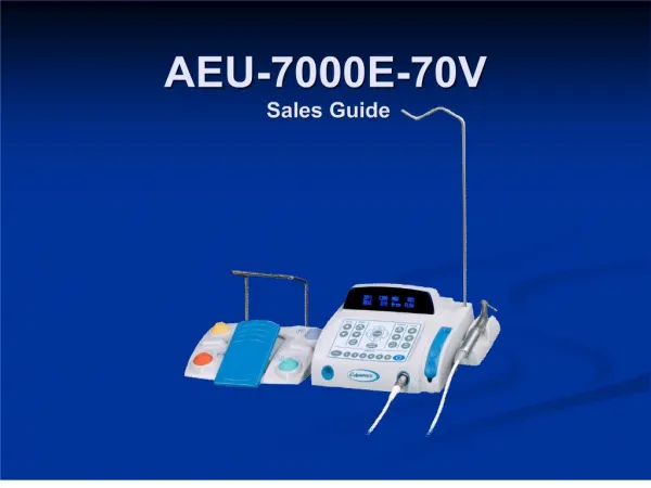
70V Systems Steve Brooks Atlas Sound Tech Support Manager
InfoComm International Brings You AND Career Development ■ News Network Industry Awareness ■ Market Research Integrated Systems Events ■ Certification
Stay informed! Sign up for… • Executive Director Randal A. Lemke’s Executive Update • InfoComm International’s e-Newsletters: http://subscribe.infocomm.org
What Are We Going To Cover In This Session? • A Few Terms Used In This Industry. • How 70V Systems Work, With a Brief Comparison Of Consumer Versus Commercial 70V Audio Systems. • What Are The Major Components In A 70V Audio System? • What Steps Does One Take In Designing A 70V Audio System? • A Brief Discussion On Loudness, With Some Examples. • The Impedance Bridge, Why You Need One.
Let’s Review Some Of The Terminology • Constant Voltage - • A Name Given To A General Practice Begun In The Late 1920 And Early 1930’s Governing the Interface Between Amplifiers And Loudspeakers Used For Public Address Systems. • Early Sound System Engineers (Geeks Today!) Looked At this Country’s Electrical Power Distribution System And Used Their Practice Of Distributing Power, Not Voltage.
Constant Voltage The Key Here Is That Power = Voltage x Current. Example - I Want 100W Delivered to My House. Here Are Two Ways To Do This. 10V x 10A = 100W (Low Voltage x High Current) Large Cable Needed Here To Carry The High Current!
Constant Voltage Or, I Could Achieve The Same Result By… 100V x 1A = 100W (High Voltage x Low Current) I Can Reduce The Wire Diameter And Still Get 100W To My House!
More Terminology.. • Commercial Audio System - An audio system used in commercial spaces, typically used for paging, signaling, Voice Evac and background music. • Distributed Audio System - See Commercial Audio System. • BGM - “Background Music”. Music that is played in an office or store at a low level, designed to enhance worker productivity or the shopping experience.
Terminology…….. • 25/70/100V Audio Systems- Refers To The Maximum Output Voltage Of The Amplifier In The System. - 25V Systems Are Typically Found In Schools And Prisons. Considered Low Voltage, Conduit Typically Not Required. - 70V Is The Most Common, May Or May Not Require Conduit For The Speaker Lines. - 100V Is Used Where Very Long Speaker Runs Are Necessary, The Higher Voltage Results In Lower Current In The Speaker Line, Resulting In Smaller Gauge Wire Needed.
Where Did 70 Volts Come From? • Sometime In The Late 1940’s, UL Stated That All Voltages Above 100V Peak Will Be Installed In Conduit. • To Get Around This And Reduce Install Costs, We Look At the “RMS” Or Average Of 100V. • Vrms = .707 X Vpeak • .707 x 100 = 70.7V!- No Conduit!
Terminology…….. • Transformer Taps- Refers To The Amount Of Power To Be Delivered To A Commercial Loudspeaker, i.e.: 1W, 2W, 5W. The Higher The Number, The Louder The Speaker Will Be. • Auto Former - A Specific Type Of Transformer, Used On Attenuators (Volume Controls) In A Commercial Audio System. Also Available As A Stand Alone Product, Used For Stepping Up/Down Voltage And Impedance.
Consumer Versus Commercial • A Typical “Consumer” Home System 8 Ohm loudspeakers This System Has 2 Speakers Connected, Usually Up To 4 Maximum CD Player Integrated receiver Assuming This Is A 100W Receiver And It Is Delivering Maximum Power, We Would “See” About 28VAC At The Speaker Terminals. Remember This Number.
Consumer Versus Commercial A Typical Commercial BGM and Paging System Paging Microphone Commercial grade 70V ceiling speakers CD Player-BGM Source This Amplifier Is Rated At 120W. At Maximum Power, We See 70VAC At The Speaker Terminals. Commercial Grade 70V Mixer Amplifier
What’s The difference? • The Home System Can Only Have A Few Speakers Connected. • The Home System Can’t Work With Long Speaker Wire Runs Without Using Very Large Diameter Cable, Due To Voltage Drops In The Cable. • The Commercial System Can Have Lots Of Speakers Attached To The Amplifier. • The Commercial System Can Use Smaller Speaker Wire.
So, How Do We Accomplish This? By The Use Of Step Up And Step Down Transformers………………… We “Step Up” The Voltage/Impedance (Audio Signal) Which Lowers The Current Coming Out Of The Amplifier, And “Step Down” The Voltage/Impedance (And Raise The Current Back Up) To The Loudspeakers! Power Companies Do This Everyday, They Step Up The Voltage On The Power Lines For Distribution, Then Step It Back Down At Your Home! Let’s Take A Closer Look At Transformers!
Loudspeaker Transformers Typical 8W 70V step down transformer, usually mounted on the loudspeaker Primary Secondary Low Voltage, High Current To Speaker High Voltage, Low Current From 70V Amplifier Taps Set The Amount Of Power The Speaker Will Draw From The Amp
70V Amplifier With Internal Transformer Shown Internal 25/70/100V Transformer To 70V Loudspeakers
One Final Word About Transformers • Besides Stepping Up/Down The Voltage, They Also Step Up/Down The Impedance Of The Amplifier’s Output And Speakers. • By Raising The Impedance, We Can Now Attach Lots Of Speakers In Parallel, Without Causing The Amplifier To “See” Too Low Of A Load At The Speaker Terminals.
Next Up Now Let’s Take A Look At The Major Components In A 70V System….
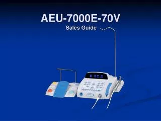
Amplifiers/Mixer Amplifiers 70V Power Amps Small Mixer Amps Large Mixer Amps Power Amps And Mixer Amps?? What’s The Difference?
Here Is The Difference.. • Power Amplifiers Typically Don’t Have A Microphone Preamp And Accept Line level Signals Only. Usually Have Multiple Channels. • Usually Have A Separate Mixer Connected To The Inputs. ----------------------------------------------------------------------------------- • Mixer Amps Have A Preamp and A Power Amp Section And Typically Accept Multiple Line Level And Microphone Level Signals. • Mixer Amps Usually Have Tone Controls (Bass/Treble) Included.
Loudspeakers 4” Ceiling Speaker With Tweeter High Power Ceiling Speaker 4” Ceiling Speaker “Pendant” Type Speaker Paging Horn Surface Mount Speaker High Power Stadium Horn
Attenuators Since We May Need A Way To Control The Loudness Of the Speakers, We Install Attenuators. 70V Attenuators Are Wired Into The Speaker Line, And Are Rated On How Much Power (Speaker Qty. x Tap Setting) They Can Deliver To The Speakers Connected!
While We Are On The Subject • How Do We Wire Attenuators To Control The Volume Of Just One Speaker On A 70V Line?
Wiring A 70V Attenuator One Loudspeaker
Wiring A 70V Attenuator Two Volume Controls
Designing An Audio System • Some Things To Consider.. • SPL - How Loud Does It Really Need To Be To Overcome The Ambient Noise Levels? • Coverage - Where Does The Page Need To Be Heard? • Frequency Response - Paging or BGM or Both? Background Music or Foreground Music? • Power - How Large Will Our Amplifier Need To be? • Important!What Does The Customer Want Or Expect?
Selecting A Loudspeaker • Will They Be Installed Inside or Outside? • Will They Be Installed Flush or Surface Mounted? • What Is The Ambient Noise Level The Speaker Must Overcome? • How Far Will The Speaker Be From The Listener? • What Type Of Sound Quality Is The Customer Expecting?
Choosing A Loudspeaker Paging Horns - Used Indoors And Out, Very Efficient, Voice Only Surface Mount - Used Indoors, Voice & Music Ceiling Mount - Used Indoors, Voice & Music
Choosing A Loudspeaker Coaxial Indoor/Outdoor Speaker - Voice & Music
How Many Loudspeakers Do I Need? We Have Chosen The Amplifier And The Loudspeaker, Now, How Many Will I Need? Always Measure The Dimensions Of The Spaces Needing Audio. - Room Length? - Room Width? - Room Height To Ceiling? - Will Occupants Be Seated Or Standing?
What Is One Of The Most Important Things To Consider When Designing An Audio System? • The Customers Ability To Pay For It? • Can I Get 60 Day Terms From My Vendors? • Proper Loudspeaker Spacing? • Does The Customer Get The Keys To The Equipment Rack? Answer…. Proper Speaker Spacing!
Loudspeakers - How Many?Here Is The Hard Way To Calculate. 6” Speaker in a 10ft ceiling r = (10-5) tan 110/2 r= 7.14
Don’t Have Time To Do The Math? Most Speaker Manufacturers Provide A Ceiling Speaker Calculator On Their Website! Make Use Of It!
We Should Look At Three Accepted Ceiling Speaker Spacing Scenarios Each Type Has Its’ Own Pros And Cons Let’s Start With……
Edge To Edge Ceiling Layout Notice The Large Gaps In The Coverage? -6dB Down Point For The Loudspeaker Or ¼ The Power 14’ On Center
Minimum Overlap Speaker Layout See the overlap between adjacent speakers? 10’ on center
Edge To Edge Layout Our customers may not want a system with this much density, nor would they want to pay for it! Lots Of Overlap Between Speakers 7’ On Center
How Loud Does The System Need To Be? • The System Only Needs To Be Loud Enough! • Typically, We Shoot For Minimum 6dB Above Ambient Noise Levels, 10dB Is Better. • It Is Much Easier To Turn Down The System At The Amplifier Than It Is To Go And Re-Tap All The speakers Up!
Let’s talk About Loudness This One Goes To “11”!
SPL Design Goals Typical 8” Ceiling Speakers Here, Tapped At ¼ to1W. Paging Horns Required Here Be Careful If SPL Is Above 100dB!
Loudspeaker Wire • 70V Speakers Are Always Wired In Parallel, (+) To (+), (-) To (-). • Use Stranded Wire, Do Not Use Voice And Data Wire (CAT5). Solid Core Data Wire Is Too Small And Can Be Unreliable When Twisted • Typically, 2 Conductor, Stranded Of Sufficient Capacity For Speaker Lines • 18 Gauge, 2 Conductor Stranded Is Most Common For Small To Mid Size Systems. Shielded Cable Is Unnecessary!
Calculating The Proper Size Wire If You Are Unsure, Or Have An Install With Many Loudspeakers And Long Speaker Runs… Then… We Need To Determine The Wire Size For This Job. It’s Best To Calculate The Total Speaker Load That The Amplifier Will Be Required To Drive AND The Total Wire Length.
Calculating The Load Impedance • The Formula For Calculating The Total Load Impedance Comes From Ohms Law. • Zt=E² / P • Zt Is The Total Impedance You Are Looking For • E² = 70.7 X 70.7 or 5000 • P = The Number Of Speakers X The Tap Setting
Let’s Look At An Example Example: • A system has 50 speakers, all tapped at 5W each. So, 5 X 50 = 250, this is “P” in the equation, and we already know E² = 5000. So, divide 5000 by 250, and the answer is………..20 Ω impedance! • Zt = E² / P • The Total Speaker Load That The Amplifier “Sees” Is 20Ω.
Now We Factor In The Speaker Wire.. • Load Impedance = 20 ohms • Speaker run is 200 feet, and wire specified (14 gauge) has a resistance of .0025 ohms per foot. So, multiply .0025 X 200 X 2 = 1 ohm. The 2 in the equation is for the “loop” length, out and back. • Add The 1 Ohm To Our 20 Ohms = 21 Ohms • Looking at the wire gauge chart, I see that we will have -.4dB loss, which is acceptable with this wire and speaker load!