
Transmitters
E N D
Presentation Transcript
5 Transmitters
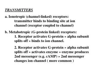
AM Transmitted Systems • Modulator Circuits • Amplitude modulation (AM) generated as result of mixing or combining carrier and intelligence frequencies within nonlinear device or circuit. • Modulator • Transmitter mixer circuit designed to produce modulation directly. • Modulation type • Where intelligence is injected.
AM Transmitted Systems • Neutralization • Vacuum tubes still found in areas of electronic communications. • Neutralizing capacitor • Path for return of a signal 180° out of phase with signal returned from plate to grid. • Self-oscillation a problem for all RF amplifiers.
AM Transmitted Systems • High- and Low-Level Modulation • High-level modulation scheme • Intelligence added at last possible point before transmitting antenna. • Low-level modulation • Intelligence injected at a point before final output stage. • Choice of high- or low-level modulation driven by required power output and trade-offs.
AM Transmitted Systems • Transistor High-Level Modulator • Class-C operation provides abrupt nonlinearity when device switches on and off. • This is in contrast to gradual nonlinearities offered by transistor at high and low levels of class A bias.
AM Transmitter Measurements • Trapezoid Patterns • Standard oscilloscope display of transmitted AM signal will indicate any gross deficiencies. • Technique is better if dual-trace scope used to allow intelligence signal to be superimposed on AM signal. • Trapezoidal pattern • Improvement to this method.
AM Transmitter Measurements • Meter Measurement • It is possible to make transmitter checks with a dc ammeter in collector of modulated stage.
AM Transmitter Measurements • Spectrum Analyzers • Transmitter troubleshooting in frequency domain reliant on spectrum analyzers for determining spectral characteristics of output and identifying unwanted and potentially interfering frequency components.
AM Transmitter Measurements • Harmonic Distortion Measurements • Made by applying spectrally pure signal source to device under test (DUT). • Quality of measurement dependent on harmonic distortion of signal source and spectrum analyzer. • Source provides signal to DUT; spectrum analyzer used to monitor output.
AM Transmitter Measurements • Special RF Signal Measurement Precautions • Effects must be understood when testing RF signals as compared to audio frequencies. • Loading of high-Q parallel-resonant circuits by relatively low impedance instrument. • Frequency response shift caused by test lead and instrument input capacitance.
AM Transmitter Measurements • Measuring Transmitter Output Power • Dummy antenna • Resistive load used in place of regular antenna. • Prevents undesired transmissions that may otherwise occur and damage to output circuits that may occur under unloaded conditions.
SSB Transmitters • Filter Method • Unwanted sideband suppressed. • Traditional method; widely used in analog SSB applications. • Phase Method • Phase discrimination may be used to cancel one sideband of DSB signal. • Sine and cosine waves lend themselves to digital processing techniques.
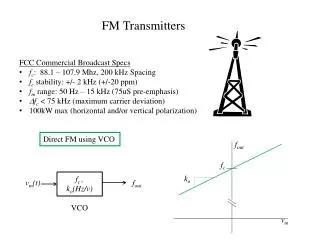
FM Transmitters • Composed of oscillators, amplifiers, filters, and modulating stages. • Direct FM Generation • Frequency of carrier oscillator directly varied by modulating signal. • Varactor diode used to generate FM directly. • Reactance modulator • Transistor made to function as variable capacitance.
FM Transmitters • Direct FM Generation • Crosby systems • FM systems utilizing direct generation with AFC. • Exciter • Circuitry that generates modulated signal. • Discriminator • Opposite of a VCO; provides a dc level output based on frequency input.
FM Transmitters • Indirect FM Generation • Armstrong • Modulation of stable crystal oscillator without cumbersome AFC circuitry; provides carrier accuracies identical to crystal accuracy. • Indirectly generates FM by changing the phase of a crystal oscillator’s output.
FM Transmitters • Indirect FM Generation • Not capable of much frequency deviation. • Dynamic action of phase detector/VCO and feedback path is basis of a PLL.
Stereo FM • Stereo radio broadcast • Two separate 30-Hz to 15-kHz signals used to modulate the carrier. • Stereo transmitter has modulating signal. • Frequency-division multiplexing • Two different signals multiplexed together by having them coexist in two different frequency ranges. • Stereo FM more prone to noise than monophonic (monaural) broadcasts.